Infiniti G20 (P11). Manual - part 318
Trouble Diagnoses
NCEL0021
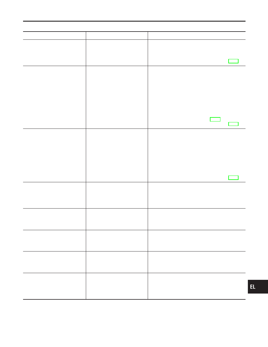
Symptom
Possible cause
Repair order
Neither headlamp operates.
1. 10A fuse
2. Lighting switch
3. Headlamp battery saver control
unit
1. Check 10A fuse [No. 24, located in fuse block (J/B)].
Verify battery positive voltage is present at terminal
7 of headlamp battery saver control unit.
2. Check lighting switch.
3. Check headlamp battery saver control unit. (EL-37)
LH headlamp (low and high beam)
does not operate, but RH head-
lamp (low and high beam) does
operate.
1. 15A fuse
2. Headlamp LH relay
3. Headlamp LH relay circuit
4. LH headlamp ground circuit
5. Lighting switch
6. Daytime light control unit
7. Headlamp battery saver control
unit
1. Check 15A fuse (No. 32, located in fusible link and
fuse box). Verify battery positive voltage is present
at terminals 1 and 3 of headlamp LH relay.
2. Check headlamp LH relay.
3. Check the following.
a. Headlamp LH relay and lighting switch.
b. Headlamp LH relay and headlamp battery saver
control unit.
4. Check harness between LH headlamp and daytime
light control unit.
5. Check lighting switch.
6. Check daytime light control unit. (EL-50)
7. Check headlamp battery saver control unit. (EL-37)
RH headlamp (low and high beam)
does not operate, but LH head-
lamp (low and high beam) does
operate.
1. 15A fuse
2. Headlamp RH relay
3. Headlamp RH relay circuit
4. RH headlamp ground circuit
5. Lighting switch
6. Headlamp battery saver control
unit
1. Check 15A fuse (No. 33, located in fusible link and
fuse box). Verify battery positive voltage is present
at terminals 1 and 3 of headlamp RH relay.
2. Check headlamp RH relay.
3. Check the following.
a. Headlamp RH relay and lighting switch.
b. Headlamp RH relay and headlamp battery saver
control unit.
4. Check harness between RH headlamp and ground.
5. Check lighting switch.
6. Check headlamp battery saver control unit. (EL-37)
LH high beam does not operate,
but LH low beam does operate.
1. Bulb
2. Open in LH low beams circuit
3. Lighting switch
1. Check bulb.
2. Check the following.
a. Lighting switch and daytime light control unit.
b. Daytime light control unit and LH headlamp.
3. Check lighting switch.
LH low beam does not operate, but
LH high beam does operate.
1. Bulb
2. Open in LH low beams circuit
3. Lighting switch
1. Check bulb.
2. Check harness between lighting switch and LH
headlamp.
3. Check lighting switch.
RH high beam does not operate,
but RH low beam does operate.
1. Bulb
2. Open in RH low beams circuit
3. Lighting switch
1. Check bulb.
2. Check harness between lighting switch and RH
headlamp.
3. Check lighting switch.
RH low beam does not operate,
but RH high beam does operate.
1. Bulb
2. Open in RH low beams circuit
3. Lighting switch
1. Check bulb.
2. Check harness between lighting switch and RH
headlamp.
3. Check lighting switch.
High beam indicator does not
work.
1. Bulb
2. Ground circuit
3. Open in high beam circuit
1. Check bulb in combination meter.
2. Check harness between high beam indicator and
ground.
3. Check harness between lighting switch and combi-
nation meter.
GI
MA
EM
LC
EC
FE
CL
MT
AT
AX
SU
BR
ST
RS
BT
HA
SC
IDX
HEADLAMP (FOR CANADA) — DAYTIME LIGHT SYSTEM —
Trouble Diagnoses
EL-49