Infiniti G20 (P11). Manual - part 300


  Index      Infiniti     Infiniti G20 (P11) - service repair manual 1999-2002 year


Search            


Content   ..  298  299  300  301   ..


Infiniti G20 (P11). Manual - part 300


8

CHECK FUEL PUMP RELAY-2

Refer to “Component Inspection”, EC-613.

OK or NG

OK

©

GO TO 15.

NG

©

Repair or replace fuel pump relay-2.
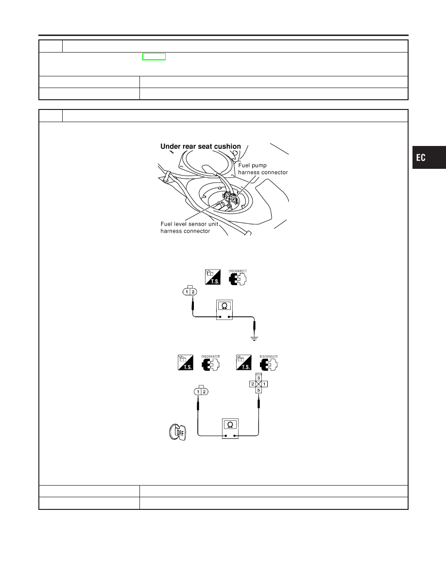
9

CHECK POWER GROUND CIRCUIT

1. Turn ignition switch “OFF”.
2. Disconnect fuel pump harness connector.

SEF299WA

3. Check harness continuity between fuel pump terminal 2 and body ground, fuel pump terminal 1 and fuel pump relay-1

terminal 5.

AEC758

Continuity should exist.

4. Also check harness for short to ground and short to power.

OK or NG

OK

©

GO TO 11.

NG

©

GO TO 10.

GI

MA

EM

LC

FE

CL

MT

AT

AX

SU

BR

ST

RS

BT

HA

SC

EL

IDX

FUEL PUMP

Diagnostic Procedure (Cont’d)

EC-611

10

DETECT MALFUNCTIONING PART

Check the following.

I

Harness connectors M74, B102

I

Harness for open or short between fuel pump and body ground

I

Harness for open or short between fuel pump and fuel pump relay-1

©

Repair open circuit or short to ground or short to power in harness or connectors.

11

CHECK OUTPUT SIGNAL CIRCUIT

1. Disconnect ECM harness connector.
2. Check harness continuity between ECM terminal 21 and fuel pump relay-1 connector terminal 2.

Refer to Wiring Diagram.

Continuity should exist.

3. Also check harness for short to ground and short to power.

OK or NG

OK

©

GO TO 13.

NG

©

GO TO 12.

12

DETECT MALFUNCTIONING PART

Check the following.

I

Harness connectors M49, F23

I

Harness for open or short between ECM and fuel pump relay-1

NG

©

Repair open circuit or short to ground or short to power in harness or connectors.

13

CHECK FUEL PUMP RELAY-1

Refer to “Component Inspection”, EC-613.

OK or NG

OK

©

GO TO 14.

NG

©

Replace fuel pump relay-1.

14

CHECK FUEL PUMP

Refer to “Component Inspection”, EC-613.

OK or NG

OK

©

GO TO 15.

NG

©

Replace fuel pump.

15

CHECK INTERMITTENT INCIDENT

Perform “TROUBLE DIAGNOSIS FOR INTERMITTENT INCIDENT”, EC-146.

©

INSPECTION END

FUEL PUMP

Diagnostic Procedure (Cont’d)

EC-612

SEF511P

Component Inspection

=NCEC0449

FUEL PUMP RELAY-1 AND -2

NCEC0449S01

Check continuity between terminals 3 and 5.

Conditions

Continuity

12V direct current supply between terminals 1 and 2

Yes

No current supply

No

If NG, replace relay.

SEF326W

FUEL PUMP

NCEC0449S02

1.

Disconnect fuel pump harness connector.

2.

Check resistance between terminals 1 and 2.

Resistance: 0.2 - 5.0

[at 25°C (77°F)]

If NG, replace fuel pump.

GI

MA

EM

LC

FE

CL

MT

AT

AX

SU

BR

ST

RS

BT

HA

SC

EL

IDX

FUEL PUMP

Component Inspection

EC-613

Power steering oil pressure
switch harness connector

RH strut tower

SEF327W

Component Description

NCEC0451

The power steering oil pressure switch is attached to the power
steering high-pressure tube and detects a power steering load.
When a power steering load is detected, it signals the ECM. The
ECM adjusts the IACV-AAC valve to increase the idle speed and
adjust for the increased load.

CONSULT-II Reference Value in Data Monitor
Mode

NCEC0452

Specification data are reference values.

MONITOR ITEM

CONDITION

SPECIFICATION

PW/ST SIGNAL

I

Engine: After warming up, idle
the engine

Steering wheel in neutral position
(forward direction)

OFF

The steering wheel is fully turned

ON

ECM Terminals and Reference Value

NCEC0453

Specification data are reference values and are measured between each terminal and ground.

CAUTION:

Do not use ECM ground terminals when measuring input/output voltage. Doing so may result in dam-
age to the ECM’s transistor. Use a ground other than ECM terminals, such as the ground.

TERMI-

NAL

NO.

WIRE

COLOR

ITEM

CONDITION

DATA (DC Voltage)

46

SB

Power steering oil pressure
switch

[Engine is running]

I

Steering wheel is fully turned

Approximately 0V

[Engine is running]

I

Steering wheel is not turned

Approximately 5V

POWER STEERING OIL PRESSURE SWITCH

Component Description

EC-614


Content   ..  298  299  300  301   ..