Infiniti G20 (P11). Manual - part 271


  Index      Infiniti     Infiniti G20 (P11) - service repair manual 1999-2002 year


Search            


Content   ..  269  270  271  272   ..


Infiniti G20 (P11). Manual - part 271


5

DETECT MALFUNCTIONING PART

Check the following.

I

Harness connectors F6, E123

I

Harness for open or short between crankshaft position sensor (OBD) and ECM

I

Harness for open or short between crankshaft position sensor (OBD) and TCM (Transmission control module)

©

Repair open circuit or short to power in harness or connectors.
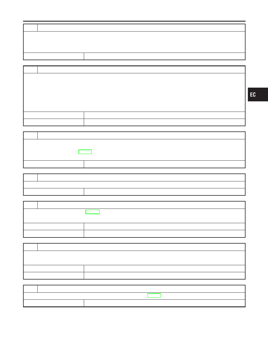
6

CHECK SHIELD CIRCUIT

1. Disconnect harness connectors F6, E123.
2. Check harness continuity between harness connector F6 terminal 8 and engine ground.

Refer to Wiring Diagram.

Continuity should exist

3. Also check harness for short to power.
4. Then reconnect harness connectors.

OK or NG

OK

©

GO TO 8.

NG

©

GO TO 7.

7

DETECT MALFUNCTIONING PART

Check the following.

I

Harness connectors F6, E123

I

Joint connector-1 (Refer to EL-274, “HARNESS LAYOUT”.)

I

Harness for open or short between harness connector F6 and engine ground

©

Repair open circuit or short to ground or short to power in harness or connectors.

8

CHECK IMPROPER INSTALLATION

Loosen and retighten the fixing bolt of the crankshaft position sensor (OBD). Then retest.

Trouble is not fixed.

©

GO TO 9.

9

CHECK CRANKSHAFT POSITION SENSOR (OBD)

Refer to “Component Inspection”, EC-496.

OK or NG

OK

©

GO TO 10.

NG

©

Replace crankshaft position sensor (OBD).

10

CHECK GEAR TOOTH

Visually check for chipping flywheel or drive plate gear tooth (cog).

OK or NG

OK

©

GO TO 11.

NG

©

Replace the flywheel or drive plate.

11

CHECK INTERMITTENT INCIDENT

Perform “TROUBLE DIAGNOSIS FOR INTERMITTENT INCIDENT”, EC-146.

©

INSPECTION END

GI

MA

EM

LC

FE

CL

MT

AT

AX

SU

BR

ST

RS

BT

HA

SC

EL

IDX

DTC P1336 CRANKSHAFT POSITION SENSOR (CKPS) (OBD) (COG)

Diagnostic Procedure (Cont’d)

EC-495

SEF960N

Component Inspection

NCEC0333

CRANKSHAFT POSITION SENSOR (OBD)

NCEC0333S01

1.

Disconnect crankshaft position sensor (OBD) harness connec-
tor.

2.

Loosen the fixing bolt of the sensor.

3.

Remove the sensor.

4.

Visually check the sensor for chipping.

SEF231W

5.

Check resistance as shown in the figure.

Resistance: 166 - 204

[at 20°C (68°F)]

DTC P1336 CRANKSHAFT POSITION SENSOR (CKPS) (OBD) (COG)

Component Inspection

EC-496

SEF599K

Component Description

NCEC0572

The EGR temperature sensor detects temperature changes in the
EGR passage way. When the EGR volume control valve opens, hot
exhaust gases flow, and the temperature in the passage way
changes. The EGR temperature sensor is a thermistor that modi-
fies a voltage signal sent from the ECM. This modified signal then
returns to the ECM as an input signal. As the temperature
increases, EGR temperature sensor resistance decreases.
This sensor is not directly used to control the engine system. It is
used only for the on board diagnosis.

SEF068X

<Reference data>

EGR temperature

°C (°F)

Voltage*

V

Resistance

M

0 (32)

4.56

0.73 - 0.89

50 (122)

2.25

0.074 - 0.082

100 (212)

0.59

0.012 - 0.014

*: These data are reference values and are measured between ECM terminal 72
(EGR temperature sensor) and ground.
When EGR system is operating.
Voltage: 0 - 1.5V

CAUTION:

Do not use ECM ground terminals when measuring input/
output voltage. Doing so may result in damage to the ECM’s
transistor. Use a ground other than ECM terminals, such as
the ground.

On Board Diagnosis Logic

NCEC0573

Malfunction is detected when
(Malfunction A) an excessively low voltage from the EGR tem-
perature sensor is sent to ECM even when engine coolant tem-
perature is low.
(Malfunction B) an excessively high voltage from the EGR tem-
perature sensor is sent to ECM even when engine coolant tem-
perature is high.

Possible Cause

NCEC0574

MALFUNCTION A

NCEC0574S01

I

Harness or connectors (The EGR temperature sensor circuit is
shorted.)

I

EGR temperature sensor

I

Malfunction of EGR function

MALFUNCTION B

NCEC0574S02

I

Harness or connectors (The EGR temperature sensor circuit is
open.)

I

EGR temperature sensor

GI

MA

EM

LC

FE

CL

MT

AT

AX

SU

BR

ST

RS

BT

HA

SC

EL

IDX

DTC P1401 EGR TEMPERATURE SENSOR

Component Description

EC-497

I

Malfunction of EGR function

DTC Confirmation Procedure

NCEC0575

Perform “PROCEDURE FOR MALFUNCTION A” first. If 1st trip
DTC cannot be confirmed, perform “PROCEDURE FOR MAL-
FUNCTION B”.
NOTE:
If “DTC Confirmation Procedure” has been previously conducted,
always turn ignition switch “OFF” and wait at least 10 seconds
before conducting the next test.

SEF174Y

PROCEDURE FOR MALFUNCTION A

NCEC0575S01

With CONSULT-II

NCEC0575S0101

1)

Turn ignition switch “ON”.

2)

Select “DATA MONITOR” mode with CONSULT-II.

3)

Verify that “COOLAN TEMP/S” is less than 50°C (122°F).
If the engine coolant temperature is above the range, cool
the engine down.

4)

Start engine and let it idle for at least 8 seconds.

5)

If 1st trip DTC is detected, go to “Diagnostic Procedure”,
EC-501.

With GST

NCEC0575S0102

Follow the procedure “With CONSULT-II” above.

DTC P1401 EGR TEMPERATURE SENSOR

Possible Cause (Cont’d)

EC-498


Content   ..  269  270  271  272   ..