Infiniti G20 (P11). Manual - part 256
Diagnostic Procedure
NCEC0278
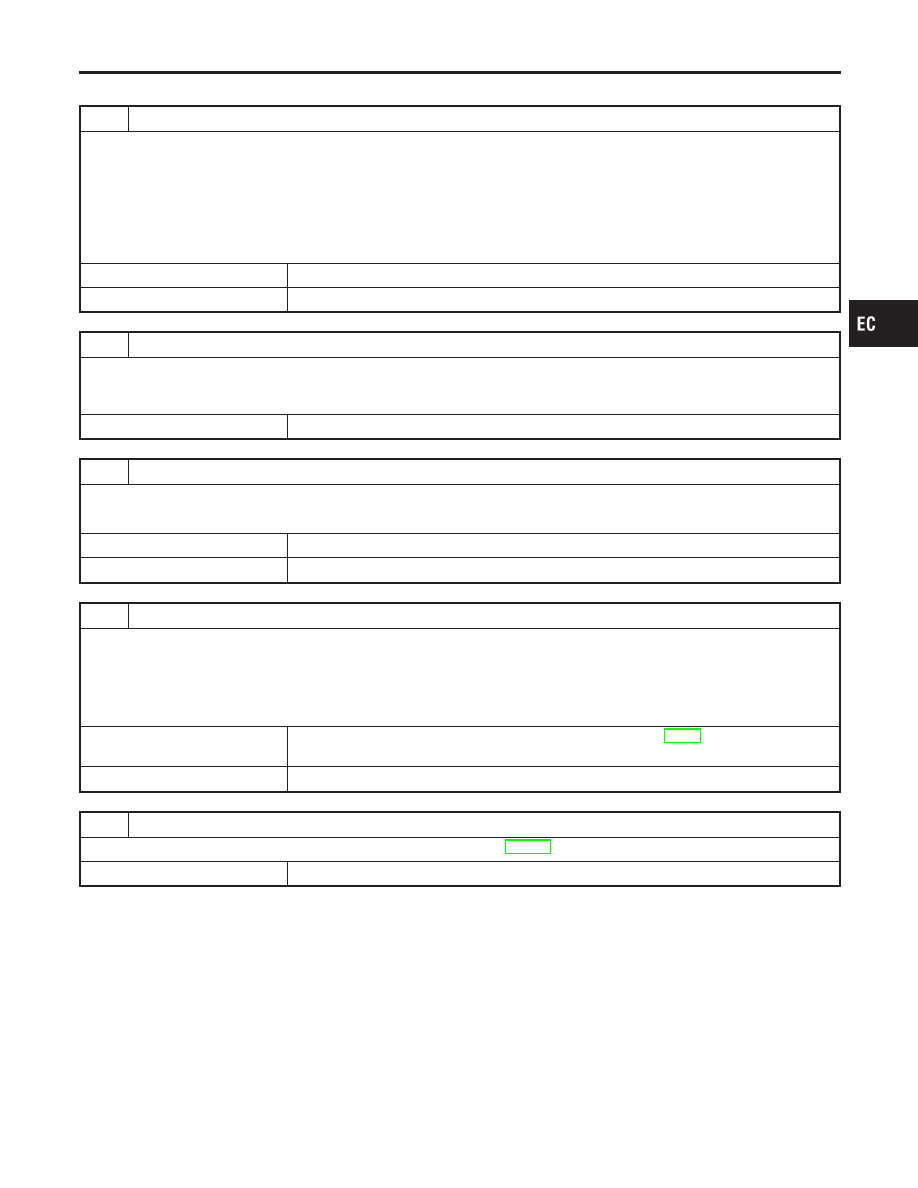
1
CHECK INPUT SIGNAL CIRCUIT
1. Turn ignition switch “OFF”.
2. Disconnect ECM harness connector and combination meter harness connector.
3. Check harness continuity between ECM terminal 86 and combination meter terminal 13.
Refer to Wiring Diagram.
Continuity should exist.
4. Also check harness for short to ground and short to power.
OK or NG
OK
©
GO TO 3.
NG
©
GO TO 2.
2
DETECT MALFUNCTIONING PART
Check the following.
I
Harness connectors F23, M49
I
Harness for open or short between ECM and combination meter
©
Repair open circuit or short to ground or short to power in harness or connectors.
3
CHECK SPEEDOMETER FUNCTION
Make sure that speedometer functions properly.
OK or NG
OK
©
GO TO 5.
NG
©
GO TO 4.
4
CHECK SPEEDOMETER CIRCUIT FOR OPEN AND SHORT
Check the following.
I
Harness connectors M6, E75
I
Harness connectors E33, E101
I
Harness for open or short between combination meter and vehicle speed sensor
OK or NG
OK
©
Check combination meter and vehicle speed sensor. Refer to EL-84, “METERS AND
GAUGES”.
NG
©
Repair open circuit or short to ground or short to power in harness or connectors.
5
CHECK INTERMITTENT INCIDENT
Perform “TROUBLE DIAGNOSIS FOR INTERMITTENT INCIDENT”, EC-146.
©
INSPECTION END
GI
MA
EM
LC
FE
CL
MT
AT
AX
SU
BR
ST
RS
BT
HA
SC
EL
IDX
DTC P0500 VEHICLE SPEED SENSOR (VSS)
Diagnostic Procedure
EC-435