Infiniti G20 (P11). Manual - part 230
Diagnostic Procedure
NCEC0211
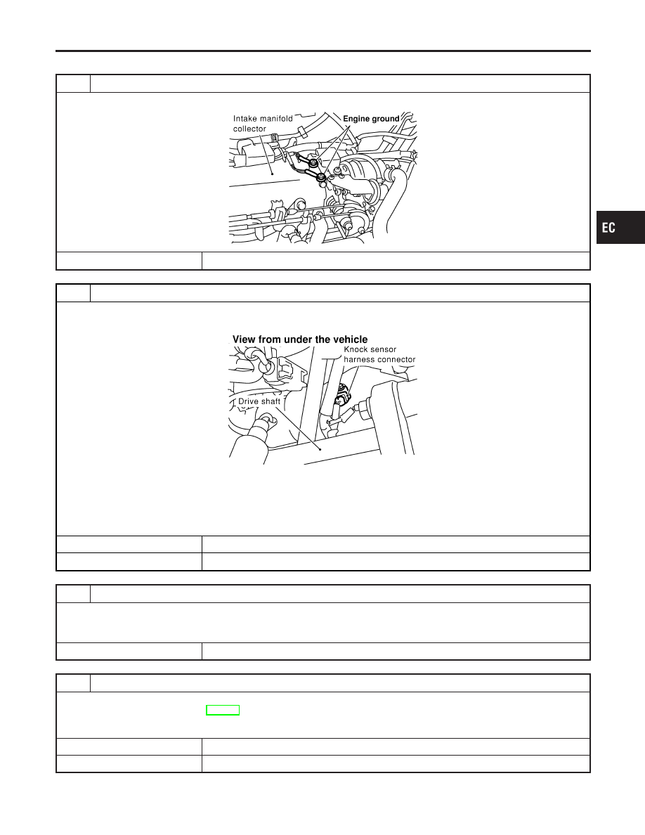
1
RETIGHTEN GROUND SCREWS
Loosen and retighten engine ground screws.
SEF839X
©
GO TO 2.
2
CHECK INPUT SIGNAL CIRCUIT-1
1. Turn ignition switch “OFF”.
2. Disconnect ECM harness connector and knock sensor harness connector.
SEF856X
3. Check harness continuity between knock sensor terminal 1 and ECM terminal 81.
Refer to Wiring Diagram.
Continuity should exist.
4. Also check harness for short to ground and short to power.
OK or NG
OK
©
GO TO 4.
NG
©
GO TO 3.
3
DETECT MALFUNCTIONING PART
Check the following.
I
Harness connectors F6, E123
I
Harness for open or short between knock sensor and ECM
©
Repair open circuit or short to ground or short to power in harness or connectors.
4
CHECK KNOCK SENSOR
Knock sensor
Refer to “Component Inspection”, EC-332.
OK or NG
OK
©
GO TO 5.
NG
©
Replace knock sensor.
GI
MA
EM
LC
FE
CL
MT
AT
AX
SU
BR
ST
RS
BT
HA
SC
EL
IDX
DTC P0325 KNOCK SENSOR (KS)
Diagnostic Procedure
EC-331