Infiniti G20 (P11). Manual - part 185


  Index      Infiniti     Infiniti G20 (P11) - service repair manual 1999-2002 year


Search            


Content   ..  183  184  185  186   ..


Infiniti G20 (P11). Manual - part 185


8

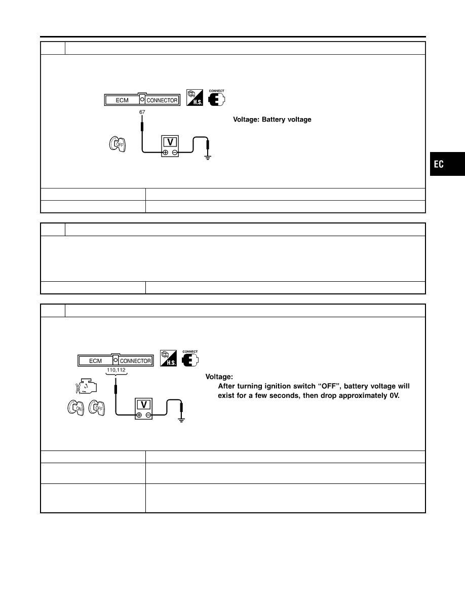
CHECK ECM POWER SUPPLY CIRCUIT-III

1. Stop engine.
2. Check voltage between ECM terminal 67 and ground with CONSULT-II or tester.

SEF293X

OK or NG

OK

©

GO TO 10.

NG

©

GO TO 9.

9

DETECT MALFUNCTIONING PART

Check the following.

I

Harness connectors M62, F24

I

Fuse block (J/B) connector M4, M5

I

7.5A fuse

I

Harness for open or short between ECM and 7.5A fuse

©

Repair harness or connectors.

10

CHECK ECM POWER SUPPLY CIRCUIT-IV

1. Turn ignition switch “ON” and then “OFF”.
2. Check voltage between ECM terminals 110, 112 and ground with CONSULT-II or tester.

SEF294X

OK or NG

OK

©

GO TO 16.

NG (Battery voltage
does not exist.)

©

GO TO 11.

NG (Battery voltage
exists for more than a
few seconds.)

©

GO TO 13.

GI

MA

EM

LC

FE

CL

MT

AT

AX

SU

BR

ST

RS

BT

HA

SC

EL

IDX

TROUBLE DIAGNOSIS FOR POWER SUPPLY

Main Power Supply and Ground Circuit (Cont’d)

EC-151

11

CHECK ECM POWER SUPPLY CIRCUIT-V

1. Disconnect ECM relay.

SEF185XA

2. Check voltage between ECM relay terminal 5 and ground with CONSULT-II or tester.

SEF916Z

OK or NG

OK

©

GO TO 13.

NG

©

GO TO 12.

12

DETECT MALFUNCTIONING PART

Check harness for open or short between ECM relay and 7.5A fuse.

©

Repair open circuit or short to ground or short to power in harness or connectors.

13

CHECK HARNESS CONTINUITY BETWEEN ECM RELAY AND ECM FOR OPEN AND SHORT

1. Check harness continuity between ECM terminals 110, 112 and ECM relay terminal 3.

Refer to WIRING DIAGRAM.

Continuity should exist.

2. Also check harness for short to ground and short to power.

OK or NG

OK

©

GO TO 15.

NG

©

GO TO 14.

14

DETECT MALFUNCTIONING PART

Check the following.

I

Harness connectors M62, F24

I

Harness for open or short between ECM and ECM relay

©

Repair open circuit or short to ground or short to power in harness or connectors.

TROUBLE DIAGNOSIS FOR POWER SUPPLY

Main Power Supply and Ground Circuit (Cont’d)

EC-152

15

CHECK ECM RELAY

1. Apply 12V direct current between ECM relay terminals 1 and 2.
2. Check continuity between ECM relay terminals 3 and 5, 6 and 7.

SEC202BC

12V (1 - 2) applied: Continuity exists.
No voltage applied: No continuity

OK or NG

OK

©

GO TO 16.

NG

©

Replace ECM relay.

16

CHECK ECM GROUND CIRCUIT FOR OPEN AND SHORT-II

1. Turn ignition switch “OFF”.
2. Disconnect ECM harness connector.
3. Check harness continuity between ECM terminals 48, 57, 106, 108 and engine ground.

Refer to Wiring Diagram.

Continuity should exist.

4. Also check harness for short to ground and short to power.

OK or NG

OK

©

GO TO 17.

NG

©

Repair open circuit or short to ground or short to power in harness or connectors.

17

CHECK INTERMITTENT INCIDENT

Perform “TROUBLE DIAGNOSIS FOR INTERMITTENT INCIDENT”, EC-146.

©

INSPECTION END

GI

MA

EM

LC

FE

CL

MT

AT

AX

SU

BR

ST

RS

BT

HA

SC

EL

IDX

TROUBLE DIAGNOSIS FOR POWER SUPPLY

Main Power Supply and Ground Circuit (Cont’d)

EC-153

SEF987W

Component Description

NCEC0050

The mass air flow sensor is placed in the stream of intake air. It
measures the intake flow rate by measuring a part of the entire
intake flow. It consists of a hot wire that is supplied with electric
current from the ECM. The temperature of the hot wire is controlled
by the ECM a certain amount. The heat generated by the hot wire
is reduced as the intake air flows around it. The more air, the
greater the heat loss.
Therefore, the ECM must supply more electric current to maintain
the temperature of the hot wire as air flow increases. The ECM
detects the air flow by means of this current change.

CONSULT-II Reference Value in Data Monitor
Mode

NCEC0051

Specification data are reference values.

MONITOR ITEM

CONDITION

SPECIFICATION

MAS A/F SE-B1

I

Engine: After warming up

I

Air conditioner switch: “OFF”

I

Shift lever: “N”

I

No-load

Idle

1.3 - 1.7V

2,500 rpm

1.8 - 2.4V

CAL/LD VALUE

I

Engine: After warming up

I

Air conditioner switch: “OFF”

I

Shift lever: “N”

I

No-load

Idle

20.0 - 35.5%

2,500 rpm

17.0 - 30.0%

MASS AIRFLOW

I

Engine: After warming up

I

Air conditioner switch: “OFF”

I

Shift lever: “N”

I

No-load

Idle

2.5 - 5.0 g·m/s

2,500 rpm

7.1 - 12.5 g·m/s

ECM Terminals and Reference Value

NCEC0052

Specification data are reference values and are measured between each terminal and ground.

CAUTION:

Do not use ECM ground terminals when measuring input/output voltage. Doing so may result in dam-
age to the ECM’s transistor. Use a ground other than ECM terminals, such as the ground.

TERMI-

NAL

NO.

WIRE

COLOR

ITEM

CONDITION

DATA (DC Voltage)

61

L

Mass air flow sensor

[Engine is running]

I

Warm-up condition

I

Idle speed

1.3 - 1.7V

[Engine is running]

I

Warm-up condition

I

Engine speed is 2,500 rpm

1.8 - 2.4V

73

G

Mass air flow sensor
ground

[Engine is running]

I

Warm-up condition

I

Idle speed

Approximately 0V

DTC P0100 MASS AIR FLOW SENSOR (MAFS)

Component Description

EC-154


Content   ..  183  184  185  186   ..