Infiniti G20 (P11). Manual - part 140
Removal and Installation
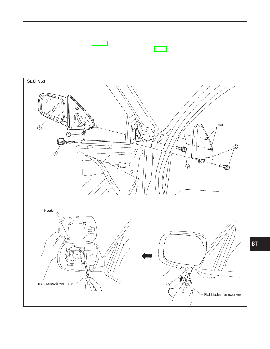
NCBT0020
CAUTION:
Be careful not to scratch door rearview mirror body.
★
For Wiring Diagram, refer to EL-143, “Wiring Diagram — MIRROR —”.
1. Remove front door trim. Refer to “DOOR TRIM” for details, BT-29.
2. Remove bolt securing inner cover, then remove inner cover.
3. Disconnect door mirror harness connector.
4. Remove door mirror harness clip.
5. Remove bolts securing door mirror, then remove door mirror assembly.
SBT418-A
GI
MA
EM
LC
EC
FE
CL
MT
AT
AX
SU
BR
ST
RS
HA
SC
EL
IDX
DOOR MIRROR
Removal and Installation
BT-55