Infiniti G20 (P11). Manual - part 111
SBR225B
Removal and Installation
NCBR0027
CAUTION:
When installing vacuum hoses, pay attention to the following
points.
I
Do not apply any oil or lubricants to vacuum hose and
check valve.
I
Insert vacuum tube into vacuum hose as shown.
I
Install check valve, paying attention to its direction.
Inspection
NCBR0028
HOSES AND CONNECTORS
NCBR0028S01
Check vacuum lines, connections and check valve for airtightness,
improper attachment chafing and deterioration.
SBR844B
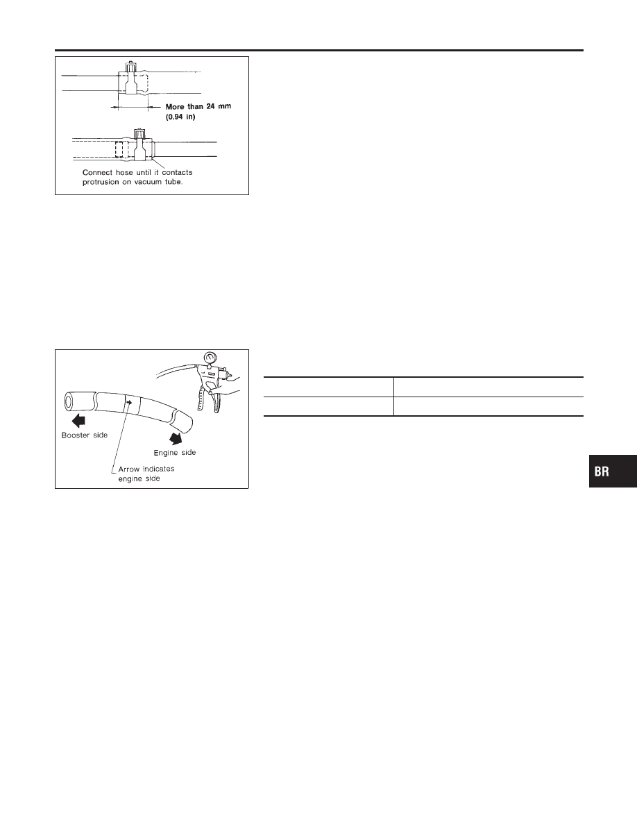
CHECK VALVE
NCBR0028S02
Check vacuum with a vacuum pump.
Connect to booster side
Vacuum should exist.
Connect to engine side
Vacuum should not exist.
GI
MA
EM
LC
EC
FE
CL
MT
AT
AX
SU
ST
RS
BT
HA
SC
EL
IDX
VACUUM HOSE
Removal and Installation
BR-19