Infiniti G20 (P11). Manual - part 102
Wheel Hub and Knuckle
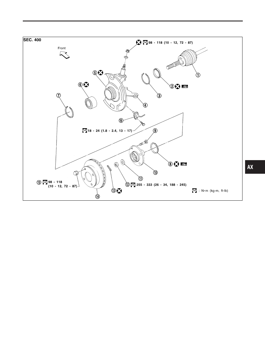
COMPONENTS
=NCAX0008
SFA809BB
1.
Drive shaft
2.
Inner grease seal
3.
Snap ring
4.
Knuckle
5.
Baffle plate
6.
Wheel bearing assembly
7.
Snap ring
8.
Outer grease seal
9.
Hub bolt
10. Wheel hub
11. Plain washer
12. Wheel bearing lock nut
13. Cotter pin
14. Brake disc
15. Wheel nut
16. ABS sensor
REMOVAL
NCAX0009
CAUTION:
Before removing the front axle assembly, disconnect the ABS
wheel sensor from the assembly. Then move it away from the
front axle assembly area.
Failure to do so may result in damage to the sensor wires and
the sensor becoming inoperative.
1.
Remove wheel bearing lock nut.
GI
MA
EM
LC
EC
FE
CL
MT
AT
SU
BR
ST
RS
BT
HA
SC
EL
IDX
FRONT AXLE
Wheel Hub and Knuckle
AX-5