Infiniti G20 (P11). Manual - part 41


  Index      Infiniti     Infiniti G20 (P11) - service repair manual 1999-2002 year


Search            


Content   ..  39  40  41  42   ..


Infiniti G20 (P11). Manual - part 41


2

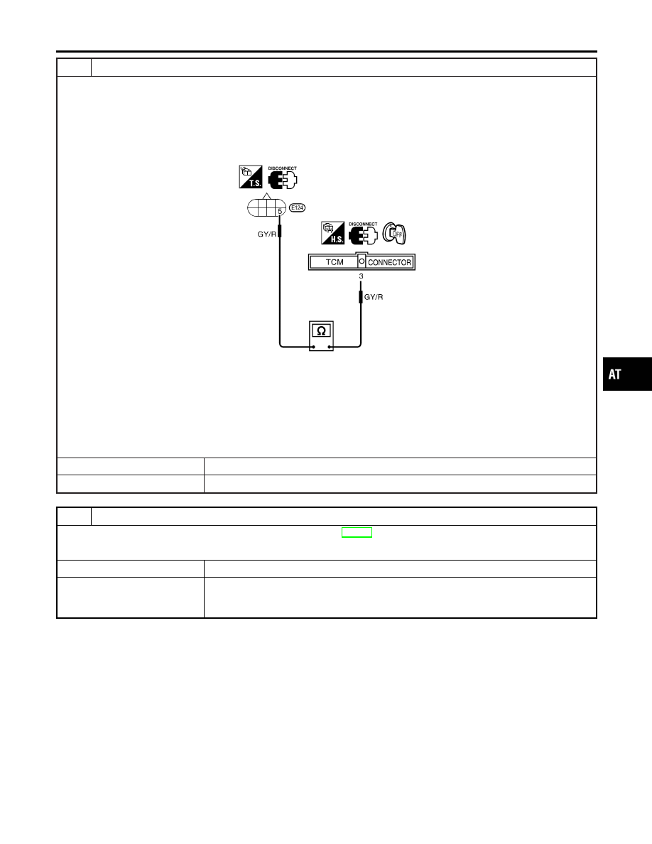
CHECK POWER SOURCE CIRCUIT

1. Turn ignition switch to “OFF” position.
2. Disconnect TCM harness connector.
3. Check continuity between terminal 5 and TCM harness connector terminal 3.

Continuity should exist.

SAT890J

If OK, check harness for short to ground and short to power.

4. Reinstall any part removed.

OK or NG

OK

©

GO TO 3.

NG

©

Repair open circuit or short to ground or short to power in harness or connectors.

3

CHECK DTC

Perform Diagnostic Trouble Code (DTC) confirmation procedure, AT-158.

OK or NG

OK

©

INSPECTION END

NG

©

1. Perform TCM input/output signal inspection.
2. If NG, recheck TCM pin terminals for damage or loose connection with harness con-

nector.

GI

MA

EM

LC

EC

FE

CL

MT

AX

SU

BR

ST

RS

BT

HA

SC

EL

IDX

DTC P0740 TORQUE CONVERTER CLUTCH SOLENOID VALVE

Diagnostic Procedure (Cont’d)

AT-161

SAT053K

Component Inspection

NCAT0057

TORQUE CONVERTER CLUTCH SOLENOID VALVE

NCAT0057S01

I

For removal, refer to AT-280.

Resistance Check

NCAT0057S0101

I

Check resistance between two terminals.

Solenoid valve

Terminal No.

Resistance

(Approx.)

Torque converter
clutch solenoid
valve

5

Ground

5 - 20

SAT054K

Operation Check

NCAT0057S0102

I

Check solenoid valve by listening for its operating sound while
applying battery voltage to the terminal and ground.

DTC P0740 TORQUE CONVERTER CLUTCH SOLENOID VALVE

Component Inspection

AT-162

Description

NCAT0058

I

This is an OBD-II self-diagnostic item and not available in TCM
self-diagnosis.

I

This malfunction will not be detected while the O/D OFF indi-
cator lamp is indicating another self-diagnosis malfunction.

I

This malfunction is detected when the A/T does not shift into
fourth gear position or the torque converter clutch does not
lock up as instructed by the TCM. This is not caused by elec-
trical malfunction (circuits open or shorted) but by mechanical
malfunction such as control valve sticking, improper solenoid
valve operation, malfunctioning oil pump or torque converter
clutch, etc.

CONSULT-II REFERENCE VALUE IN DATA MONITOR
MODE

NCAT0058S01

Remarks: Specification data are reference values.

Monitor item

Condition

Specification

Torque converter clutch solenoid valve
duty

Lock-up “OFF”

"

Lock-up “ON”

Approximately 4%

"

Approximately 94%

TCM TERMINALS AND REFERENCE VALUE

NCAT0058S02

Remarks: Specification data are reference values.

Terminal

No.

Wire color

Item

Condition

Judgement stan-

dard

(Approx.)

1

R/W

Line pressure
solenoid valve

When releasing accelerator pedal
after warming up engine.

1.5 - 2.5V

When depressing accelerator pedal
fully after warming up engine.

0V

2

P/B

Line pressure
solenoid valve
(with dropping
resistor)

When releasing accelerator pedal
after warming up engine.

5 - 14V

When depressing accelerator pedal
fully after warming up engine.

0V

3

GY/R

Torque converter
clutch solenoid
valve

When A/T performs lock-up.

8 - 15V

When A/T does not perform lock-up. 0V

GI

MA

EM

LC

EC

FE

CL

MT

AX

SU

BR

ST

RS

BT

HA

SC

EL

IDX

DTC P0744 A/T TCC S/V FUNCTION (LOCK-UP)

Description

AT-163

ON BOARD DIAGNOSTIC LOGIC

=NCAT0058S03

This diagnosis monitors actual gear position by checking the torque
converter slip ratio calculated by TCM as follows:
Torque converter slip ratio = A x C/B
A: Output shaft revolution signal from revolution sensor
B: Engine speed signal from ECM
C: Gear ratio determined as gear position which TCM supposes
If the actual gear position is much lower than the position (4th)
supposed by TCM, the slip ratio will be much less than normal. In
case the ratio does not reach the specified value, TCM judges this
diagnosis malfunction.
This malfunction will be caused when shift solenoid valve B is stuck
closed.

Gear position supposed by TCM

1

2

3

4

In case of gear position with no malfunctions

1

2

3

4

In case of gear position with shift solenoid valve B stuck closed

1

2

2

1*

*: P0744 is detected.

Diagnostic trouble code

Malfunction is detected when ...

Check items (Possible cause)

: A/T TCC S/V FNCTN

A/T cannot perform lock-up even if elec-
trical circuit is good.

I

Torque converter clutch solenoid valve

I

Line pressure solenoid valve

I

Each clutch

I

Hydraulic control circuit

: P0744

SAT014K

SAT971J

DIAGNOSTIC TROUBLE CODE (DTC) CONFIRMATION
PROCEDURE

NCAT0058S04

CAUTION:

Always drive vehicle at a safe speed.
NOTE:
If “DIAGNOSTIC TROUBLE CODE CONFIRMATION PROCE-
DURE” has been previously conducted, always turn ignition
switch “OFF” and wait at least 5 seconds before conducting
the next test.
After the repair, perform the following procedure to confirm the
malfunction is eliminated.

With CONSULT-II

1)

Start engine and select “DATA MONITOR” mode for “A/T” with
CONSULT-II.

2)

Make sure that output voltage of A/T fluid temperature sensor
is within the range below.
FLUID TEMP SEN: 0.4 - 1.5V
If out of range, drive the vehicle to decrease the voltage (warm
up the fluid) or stop engine to increase the voltage (cool down
the fluid).

3)

Select “TCC S/V FNCTN P0744” of “DTC WORK SUPPORT”
mode for “A/T” with CONSULT-II and touch “START”.

DTC P0744 A/T TCC S/V FUNCTION (LOCK-UP)

Description (Cont’d)

AT-164


Content   ..  39  40  41  42   ..