Infiniti G20 (P11). Manual - part 34


  Index      Infiniti     Infiniti G20 (P11) - service repair manual 1999-2002 year


Search            


Content   ..  32  33  34  35   ..


Infiniti G20 (P11). Manual - part 34


2

CHECK CONTROL VALVE

1. Disassemble control valve assembly. Refer to “Control Valve Assembly”, AT-312.
2. Check to ensure that:

I

Valve, sleeve and plug slide along valve bore under their own weight.

I

Valve, sleeve and plug are free from burrs, dents and scratches.

I

Control valve springs are free from damage, deformation and fatigue.

I

Hydraulic line is free from obstacles.

SAT367H

OK or NG

OK

©

GO TO 3.

NG

©

Repair control valve assembly.

3

CHECK DTC

Perform Diagnostic Trouble Code (DTC) confirmation procedure, AT-129.

OK or NG

OK

©

INSPECTION END

NG

©

Check control valve again. Repair or replace control valve assembly.

SAT050K

Component Inspection

NCAT0045

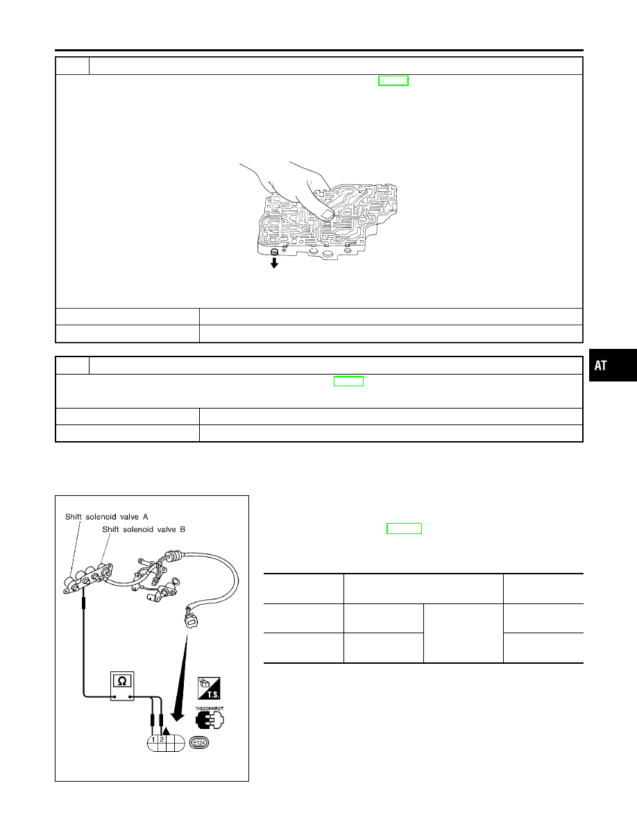
SHIFT SOLENOID VALVE A AND B

NCAT0045S01

I

For removal, refer to AT-280.

Resistance Check

NCAT0045S0101

I

Check resistance between two terminals.

Solenoid valve

Terminal No.

Resistance

(Approx.)

Shift solenoid
valve A

2

Ground

20 - 30

Shift solenoid
valve B

1

5 - 20

GI

MA

EM

LC

EC

FE

CL

MT

AX

SU

BR

ST

RS

BT

HA

SC

EL

IDX

DTC P0731 A/T 1ST GEAR FUNCTION

Diagnostic Procedure (Cont’d)

AT-133

SAT883JA

Operation Check

NCAT0045S0102

I

Check solenoid valve by listening for its operating sound while
applying battery voltage to the terminal and ground.

DTC P0731 A/T 1ST GEAR FUNCTION

Component Inspection (Cont’d)

AT-134

Description

NCAT0046

I

This is an OBD-II self-diagnostic item and not available in TCM
self-diagnosis.

I

This malfunction will not be detected while the O/D OFF indi-
cator lamp is indicating another self-diagnosis malfunction.

I

This malfunction is detected when the A/T does not shift into
second gear position as instructed by the TCM. This is not
caused by electrical malfunction (circuits open or shorted) but
by mechanical malfunction such as control valve sticking,
improper solenoid valve operation, etc.

Gear position

1

2

3

4

Shift solenoid valve A

ON (Closed)

OFF (Open)

OFF (Open)

ON (Closed)

Shift solenoid valve B

ON (Closed)

ON (Closed)

OFF (Open)

OFF (Open)

TCM TERMINALS AND REFERENCE VALUE

NCAT0046S01

Remarks: Specification data are reference values.

Terminal

No.

Wire color

Item

Condition

Judgement stan-

dard

(Approx.)

12

L/Y

Shift solenoid
valve B

When shift solenoid valve B oper-
ates.
(When driving in “D

1

” or “D

2

”.)

Battery voltage

When shift solenoid valve B does
not operate.
(When driving in “D

3

” or “D

4

”.)

1V or less

ON BOARD DIAGNOSTIC LOGIC

NCAT0046S02

This diagnosis monitors actual gear position by checking the torque
converter slip ratio calculated by TCM as follows:
Torque converter slip ratio = A x C/B
A: Output shaft revolution signal from revolution sensor
B: Engine speed signal from ECM
C: Gear ratio determined as gear position which TCM supposes
If the actual gear position is higher than the position (2nd) sup-
posed by TCM, the slip ratio will be more than normal. In case the
ratio exceeds the specified value, TCM judges this diagnosis mal-
function.
This malfunction will be caused when shift solenoid valve B is stuck
open.

Gear position supposed by TCM

1

2

3

4

In case of gear position with no malfunctions

1

2

3

4

In case of gear position with shift solenoid valve B stuck open

4

3*

3

4

*: P0732 is detected.

Diagnostic trouble code

Malfunction is detected when ...

Check items (Possible cause)

: A/T 2ND GR FNCTN

A/T cannot be shifted to the 2nd gear
position even if electrical circuit is good.

I

Shift solenoid valve B

I

Each clutch

I

Hydraulic control circuit

: P0732

GI

MA

EM

LC

EC

FE

CL

MT

AX

SU

BR

ST

RS

BT

HA

SC

EL

IDX

DTC P0732 A/T 2ND GEAR FUNCTION

Description

AT-135

SAT014K

SAT971J

SAT021J

DIAGNOSTIC TROUBLE CODE (DTC) CONFIRMATION
PROCEDURE

NCAT0046S03

CAUTION:

I

Always drive vehicle at a safe speed.

I

Be careful not to rev engine into the red zone on the
tachometer.

NOTE:
If “DIAGNOSTIC TROUBLE CODE CONFIRMATION PROCE-
DURE” has been previously conducted, always turn ignition
switch “OFF” and wait at least 5 seconds before conducting
the next test.
TESTING CONDITION:
Always drive vehicle on a level road to improve the accuracy
of test.
After the repair, perform the following procedure to confirm the
malfunction is eliminated.

With CONSULT-II

1)

Start engine and select “DATA MONITOR” mode for “A/T” with
CONSULT-II.

2)

Make sure that output voltage of A/T fluid temperature sensor
is within the range below.
FLUID TEMP SEN: 0.4 - 1.5V
If out of range, drive the vehicle to decrease the voltage (warm
up the fluid) or stop engine to increase the voltage (cool down
the fluid).

3)

Select “2ND GR FNCTN P0732” of “DTC WORK SUPPORT”
mode for “A/T” with CONSULT-II and touch “START”.

4)

Accelerate vehicle to 53 to 68 km/h (33 to 42 MPH) under the
following condition and release the accelerator pedal com-
pletely.
THROTTLE POSI: Less than 1.0/8 (at all times during step
4)
Selector lever: D position (OD “ON”)

I

Check that “GEAR” shows “3” or “4” after releasing pedal.

5)

Depress accelerator pedal to WOT (more than 7.0/8 of
“THROTTLE POSI”) quickly from a speed of 53 to 68 km/h (33
to 42 MPH) until “TESTING” changes to “STOP VEHICLE” or
“COMPLETED”. (It will take approximately 3 seconds.)
If the check result NG appears on CONSULT-II screen, go to
“DIAGNOSTIC PROCEDURE”, AT-139.
If “STOP VEHICLE” appears on CONSULT-II screen, go to
following step.

I

Check that “GEAR” shows “2” when depressing accelera-
tor pedal to WOT.

I

If “TESTING” does not appear on CONSULT-II for a long
time, select “SELF-DIAGNOSIS” for “ENGINE”. In case a
1st trip DTC other than P0732 is shown, refer to applicable
“TROUBLE DIAGNOSIS FOR DTC”.

6)

Stop vehicle.

7)

Follow the instruction displayed. (Check for normal shifting
referring to the table below.)

Vehicle condition

Gear on actual transmission shift pattern when

screen is changed to 1

,

2

,

3

,

4

No malfunction exists

1

,

2

,

3

,

4

Malfunction for P0732
exists.

4

,

3

,

3

,

4

DTC P0732 A/T 2ND GEAR FUNCTION

Description (Cont’d)

AT-136


Content   ..  32  33  34  35   ..