Infiniti G20 (P11). Manual - part 30


  Index      Infiniti     Infiniti G20 (P11) - service repair manual 1999-2002 year


Search            


Content   ..  28  29  30  31   ..


Infiniti G20 (P11). Manual - part 30


3

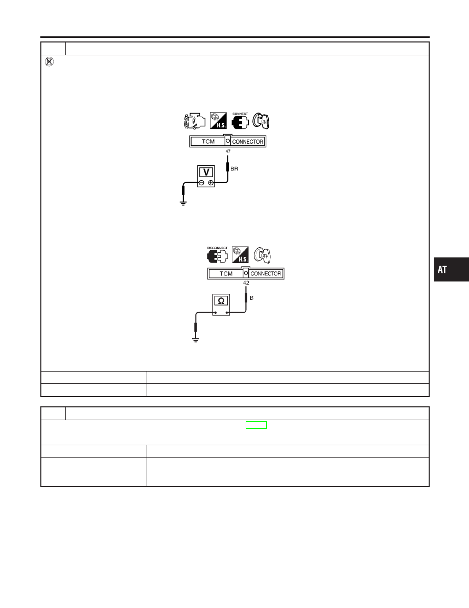
CHECK INPUT SIGNAL OF A/T FLUID TEMPERATURE SENSOR (Without CONSULT-II)

Without CONSULT-II

1. Start engine.
2. Check voltage between TCM terminal 47 and ground while warming up A/T.

Voltage:

Cold [20°C (68°F)]

Hot [80°C (176°F)]:

Approximately 1.5V

0.5V

SAT937J

3. Turn ignition switch to “OFF” position.
4. Disconnect TCM harness connector.
5. Check continuity between terminal 42 and ground.

Continuity should exist.

SAT421J

If OK, check harness for short to ground and short to power.

OK or NG

OK

©

GO TO 4.

NG

©

GO TO 5.

4

CHECK DTC

Perform Diagnostic Trouble Code (DTC) confirmation procedure, AT-114.

OK or NG

OK

©

INSPECTION END

NG

©

1. Perform TCM input/output signal inspection.
2. If NG, recheck TCM pin terminals for damage or loose connection with harness con-

nector.

GI

MA

EM

LC

EC

FE

CL

MT

AX

SU

BR

ST

RS

BT

HA

SC

EL

IDX

DTC P0710 A/T FLUID TEMPERATURE SENSOR CIRCUIT

Diagnostic Procedure (Cont’d)

AT-117

5

CHECK A/T FLUID TEMPERATURE SENSOR WITH TERMINAL CORD ASSEMBLY

1. Turn ignition switch to “OFF” position.
2. Disconnect terminal cord assembly connector in engine compartment.
3. Check resistance between terminals 6 and 7 when A/T is cold.

Resistance:

Cold [20°C (68°F)]

Approximately 2.5 k

SAT880J

4. Reinstall any part removed.

OK or NG

OK (With CONSULT-II)

©

GO TO 2.

OK (Without CONSULT-
II)

©

GO TO 3.

NG

©

1. Remove oil pan.
2. Check the following items:

I

A/T fluid temperature sensor
Refer to “Component Inspection”, AT-118.

I

Harness of terminal cord assembly for short or open

SAT298F

Component Inspection

NCAT0037

A/T FLUID TEMPERATURE SENSOR

NCAT0037S01

I

For removal, refer to AT-280.

I

Check resistance between two terminals while changing tem-
perature as shown at left.

Temperature °C (°F)

Resistance

20 (68)

Approximately 2.5 k

80 (176)

Approximately 0.3 k

DTC P0710 A/T FLUID TEMPERATURE SENSOR CIRCUIT

Diagnostic Procedure (Cont’d)

AT-118

SAT357H

Description

NCAT0038

The revolution sensor detects the revolution of the idler gear park-
ing pawl lock gear and emits a pulse signal. The pulse signal is sent
to the TCM which converts it into vehicle speed.

TCM TERMINALS AND REFERENCE VALUE

NCAT0038S01

Remarks: Specification data are reference values.

Terminal

No.

Wire color

Item

Condition

Judgement stan-

dard

(Approx.)

29

W

Revolution sensor

When moving at 20 km/h (12 MPH),
use the CONSULT-II pulse fre-
quency measuring function.*1
CAUTION:
Connect the diagnosis data link
cable to the vehicle diagnosis
connector.
*1: A circuit tester cannot be used
to test this item.

150 Hz

When vehicle parks.

Under 1.3V or
over 4.5V

42

B

Throttle position
sensor
(Ground)

ON BOARD DIAGNOSIS LOGIC

NCAT0038S02

Diagnostic trouble code

Malfunction is detected when ...

Check items (Possible cause)

: VEH SPD SEN/CIR AT

TCM does not receive the proper voltage
signal from the sensor.

I

Harness or connectors
(The sensor circuit is open or shorted.)

I

Revolution sensor

: P0720

GI

MA

EM

LC

EC

FE

CL

MT

AX

SU

BR

ST

RS

BT

HA

SC

EL

IDX

DTC P0720 VEHICLE SPEED SENSOR·A/T (REVOLUTION SENSOR)

Description

AT-119

SAT014K

SAT971J

SAT014K

SEF949Y

DIAGNOSTIC TROUBLE CODE (DTC) CONFIRMATION
PROCEDURE

NCAT0038S03

CAUTION:

I

Always drive vehicle at a safe speed.

I

Be careful not to rev engine into the red zone on the
tachometer.

NOTE:
If “DIAGNOSTIC TROUBLE CODE CONFIRMATION PROCE-
DURE” has been previously conducted, always turn ignition
switch “OFF” and wait at least 5 seconds before conducting
the next test.
After the repair, perform the following procedure to confirm the
malfunction is eliminated.

With CONSULT-II

1)

Turn ignition switch “ON” and select “DATA MONITOR” mode
for “A/T” with CONSULT-II.

2)

Drive vehicle and check for an increase of “VHCL/S SE·MTR”
value.
If the check result is NG, go to “DIAGNOSTIC PROCEDURE”,
AT-218.
If the check result is OK, go to following step.

3)

Select “DATA MONITOR” mode for “ENGINE” with CONSULT-
II.

4)

Start engine and maintain the following conditions for at least
5 consecutive seconds.
VHCL SPEED SE: 30 km/h (19 MPH) or more
THRTL POS SEN: More than 1.2V
Selector lever: D position (OD “ON”)
Driving location: Driving the vehicle uphill (increased
engine load) will help maintain the driving conditions
required for this test.
If the check result is NG, go to “DIAGNOSTIC PROCEDURE”,
AT-122.
If the check result is OK, go to following step.

5)

Maintain the following conditions for at least 5 consecutive
seconds.
CMPS·RPM (REF): 3,500 rpm or more
THRTL POS SEN: More than 1.2V
Selector lever: D position (OD “ON”)
Driving location: Driving the vehicle uphill (increased
engine load) will help maintain the driving conditions
required for this test.

With GST

Follow the procedure “With CONSULT-II”.

DTC P0720 VEHICLE SPEED SENSOR·A/T (REVOLUTION SENSOR)

Description (Cont’d)

AT-120


Content   ..  28  29  30  31   ..