Infiniti G20 (P11). Manual - part 26
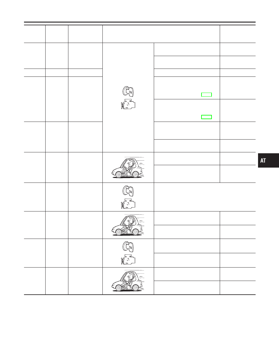
Terminal
No.
Wire color
Item
Condition
Judgement stan-
dard
(Approx.)
13
G/W
O/D OFF indica-
tor lamp
When setting overdrive control
switch in “OFF” position.
0V
When setting overdrive control
switch in “ON” position.
Battery voltage
15 *2
PU
—
—
—
16
Y
Closed throttle
position switch
(in throttle posi-
tion switch)
When releasing accelerator pedal
after warming up engine.
Refer to “TCM SELF-DIAGNOSTIC
PROCEDURE (No tools)”, AT-49.
Battery voltage
When depressing accelerator pedal
after warming up engine.
Refer to “TCM SELF-DIAGNOSTIC
PROCEDURE (No tools)”, AT-49.
0V
17
LG
Wide open
throttle position
switch
(in throttle posi-
tion switch)
When depressing accelerator pedal
more than half-way after warming
up engine.
Battery voltage
When releasing accelerator pedal
after warming up engine.
0V
18
OR
ASCD cruise
switch
When ASCD cruise is being per-
formed. (“CRUISE” light comes on.)
Battery voltage
When ASCD cruise is not being per-
formed. (“CRUISE” light does not
comes on.)
0V
19
R
Power source
Same as No. 10
20
L/B
Overrun clutch
solenoid valve
When overrun clutch solenoid valve
operates.
Battery voltage
When overrun clutch solenoid valve
does not operate.
0V
22
OR/B
Overdrive control
switch
When setting overdrive control
switch in “ON” position
Battery voltage
When setting overdrive control
switch in “OFF” position
0V
24
W/B
ASCD OD cut
signal
When “ACCEL” set switch on ASCD
cruise is in “D
4
” position.
5 - 8V
When “ACCEL” set switch on ASCD
cruise is in “D
3
” position.
0V
GI
MA
EM
LC
EC
FE
CL
MT
AX
SU
BR
ST
RS
BT
HA
SC
EL
IDX
TROUBLE DIAGNOSIS — GENERAL DESCRIPTION
TCM Terminals and Reference Value (Cont’d)
AT-101