Infiniti G20 (P11). Manual - part 17
SAT895H
GI
MA
EM
LC
EC
FE
CL
MT
AX
SU
BR
ST
RS
BT
HA
SC
EL
IDX
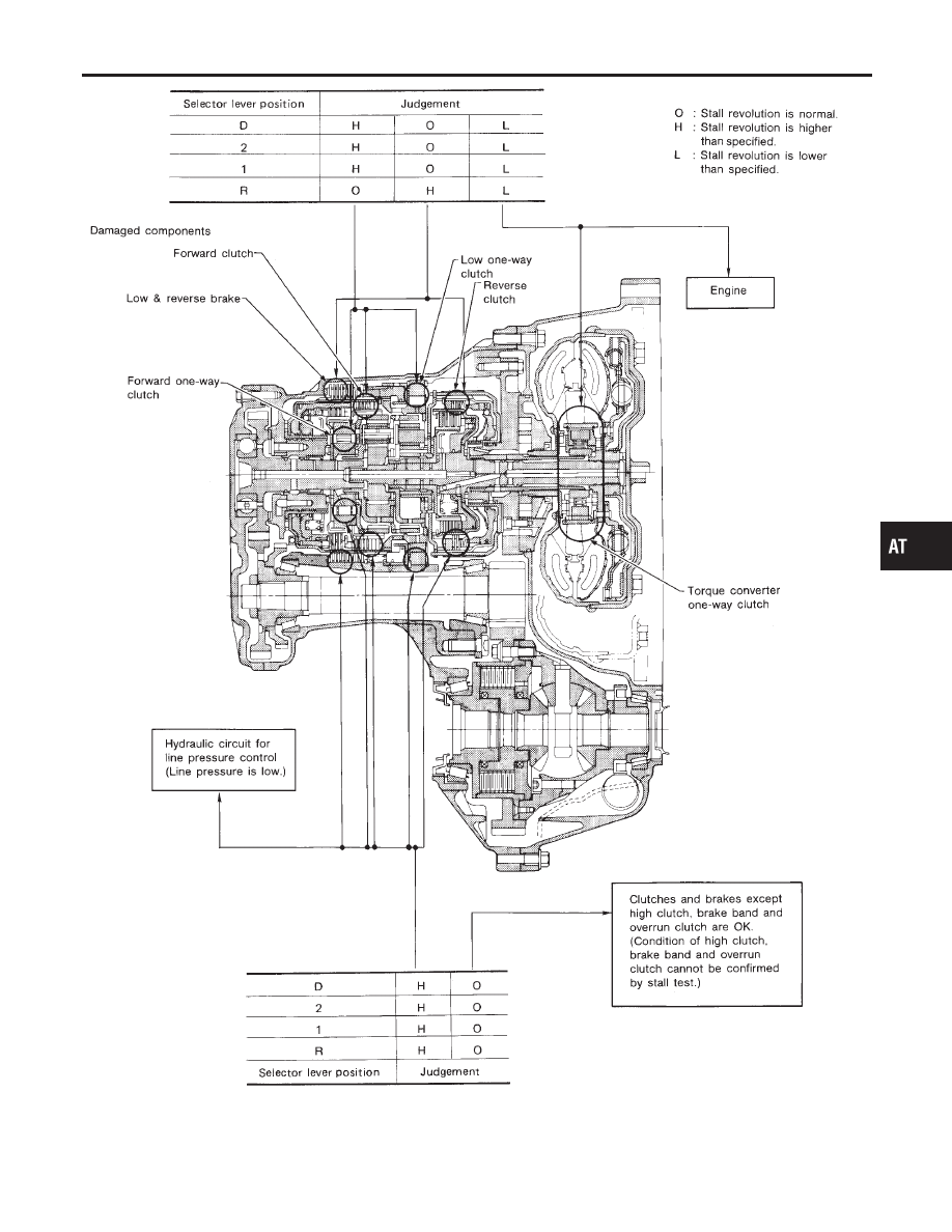
TROUBLE DIAGNOSIS — BASIC INSPECTION
Stall Test (Cont’d)
AT-65
|
|
|
SAT895H GI MA EM LC EC FE CL MT AX SU BR ST RS BT HA SC EL IDX TROUBLE DIAGNOSIS — BASIC INSPECTION Stall Test (Cont’d) AT-65 |