Infiniti G20 (P11). Manual - part 13
DTC work support item
Description
Check items (Possible cause)
4TH GR FNCTN P0734
Following items for “A/T 4th gear function (P0734)” can be con-
firmed.
I
Self-diagnosis status (whether the diagnosis is being con-
ducted or not)
I
Self-diagnosis result (OK or NG)
I
Shift solenoid valve A
I
Shift solenoid valve B
I
Overrun clutch solenoid valve
I
Line pressure solenoid valve
I
Each clutch
I
Hydraulic control circuit
TCC S/V FNCTN P0744
Following items for “A/T TCC S/V function (lock-up) (P0744)”
can be confirmed.
I
Self-diagnosis status (whether the diagnosis is being con-
ducted or not)
I
Self-diagnosis result (OK or NG)
I
Torque converter clutch sole-
noid valve
I
Each clutch
I
Hydraulic control circuit
DIAGNOSTIC PROCEDURE WITHOUT CONSULT-II
NCAT0022S07
OBD-II Self-diagnostic Procedure (With GST)
NCAT0022S0701
Refer to EC-101, section “Generic Scan Tool (GST)”.
OBD-II Self-diagnostic Procedure (No Tools)
NCAT0022S0702
Refer to EC-81, “Malfunction Indicator Lamp (MIL)”.
SAT491J
SAT851J
TCM Self-diagnostic Procedure (No Tools)
NCAT0022S0703
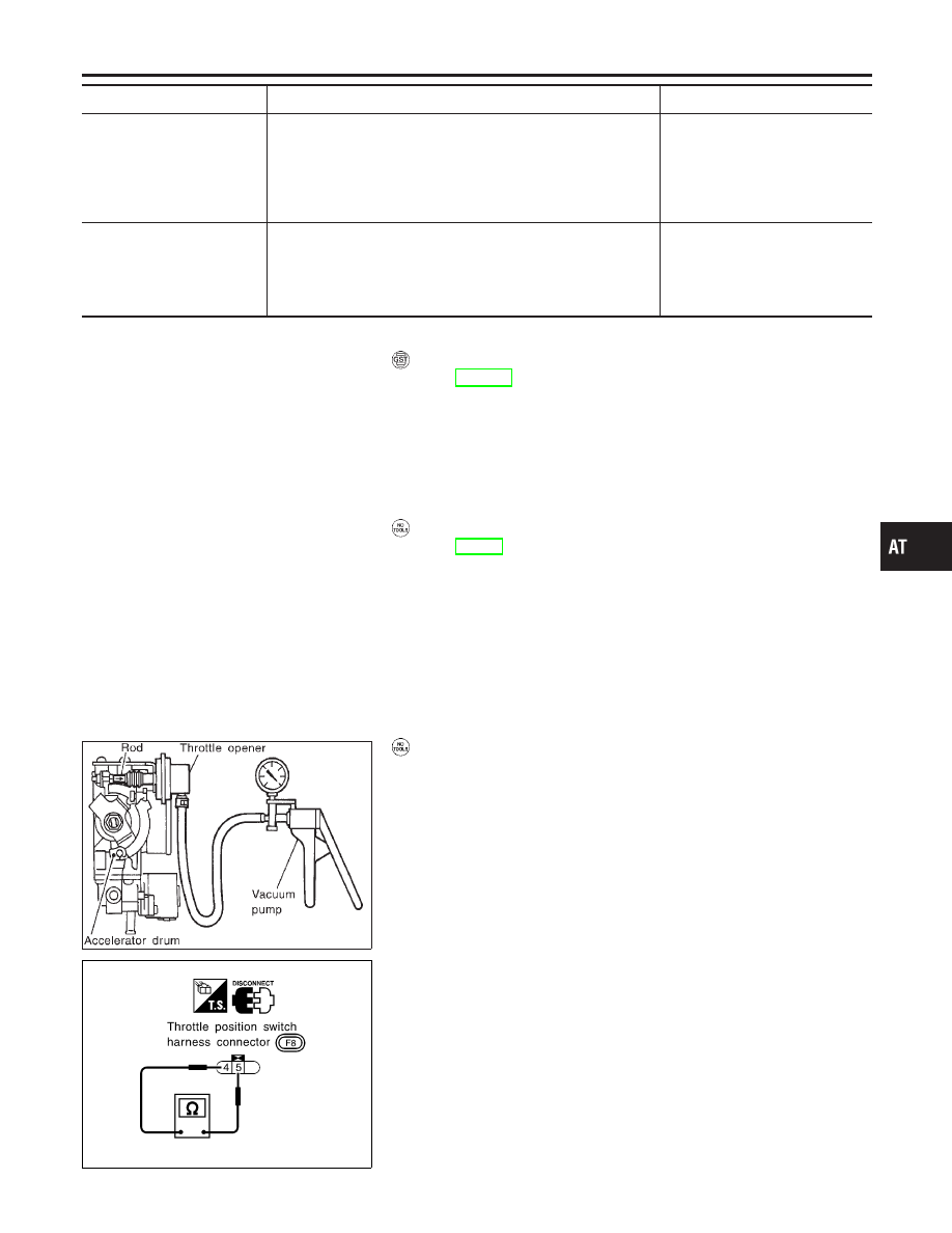
Preparation
1.
Turn ignition switch to “OFF” position.
2.
Connect the handy type vacuum pump to the throttle opener
and apply vacuum −25.3 kPa (−190 mmHg, −7.48 inHg).
3.
Disconnect the throttle position switch harness connector.
4.
Turn ignition switch to “ON” position.
5.
Check continuity of the closed throttle position switch.
Continuity should exist.
(If continuity does not exist, check throttle opener and
closed throttle position switch. Then increase vacuum
until closed throttle position switch shows continuity.)
6.
Go to “TCM self-diagnostic procedure (No tools)”.
GI
MA
EM
LC
EC
FE
CL
MT
AX
SU
BR
ST
RS
BT
HA
SC
EL
IDX
ON BOARD DIAGNOSTIC SYSTEM DESCRIPTION
CONSULT-II (Cont’d)
AT-49