Infiniti FX35 / FX45. Manual - part 954


  Index      Infiniti     Infiniti FX35 / FX45 (S50) - service repair manual 2008 year


Search            


Content   ..  952  953  954  955   ..


Infiniti FX35 / FX45. Manual - part 954


TROUBLE DIAGNOSIS FOR SYSTEM

TF-27

< SERVICE INFORMATION >

C

E

F

G

H

I

J

K

L

M

A

B

TF

N

O

P

1.

Turn ignition switch “OFF”.

2.

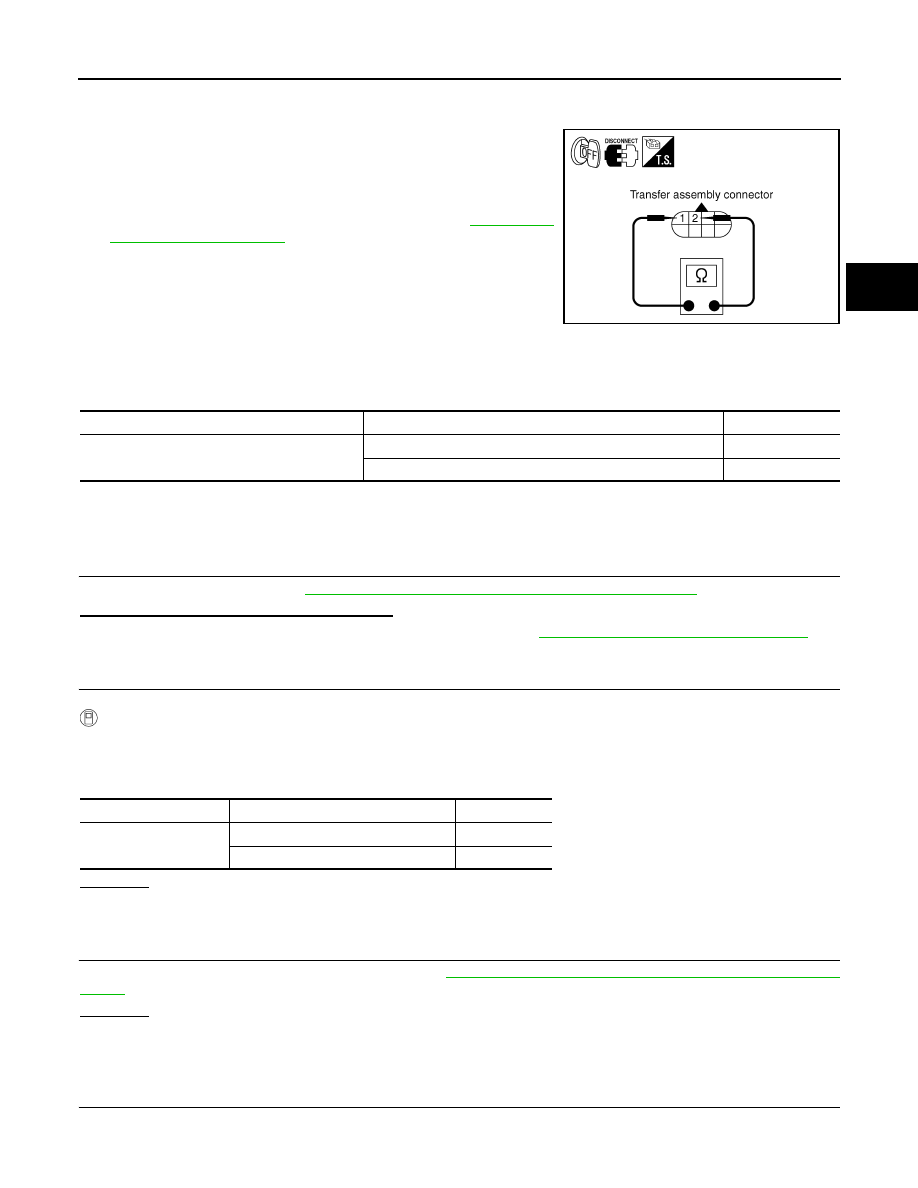
Disconnect transfer assembly harness connector. 

3.

Check resistance between transfer assembly harness connector
F43 terminals 1 and 2.

4.

If NG, replace electric controlled coupling. Refer to 

TF-40, "Dis-

assembly and Assembly"

.

DTC C1205 4WD ACTUATOR RLY

INFOID:0000000001327447

CONSULT-III REFERENCE VALUE IN DATA MONITOR MODE

Data are reference value.

DIAGNOSTIC PROCEDURE

• Check the following if “4WD ACTUATOR RLY [C1205]” is displayed in self-diagnostic results of CONSULT-

III.

1.

CHECK AWD SOLENOID SYSTEM

Perform self-diagnosis. Refer to 

TF-21, "CONSULT-III Function (ALL MODE AWD/4WD)"

.

Is the “4WD SOLENOID [C1204]” displayed?

YES

>> Perform trouble diagnosis for AWD solenoid. Refer to 

TF-25, "DTC C1204 4WD SOLENOID"

.

NO

>> GO TO 2.

2.

CHECK AWD ACTUATOR RELAY SIGNAL

 With CONSULT-III

1.

Turn ignition switch “ON”. (Do not start engine.)

2.

Select “DATA MONITOR” mode for “ALL MODE AWD/4WD” with CONSULT-III.

3.

Start engine and read out ON/OFF signal of “ETS ACTUATOR”.

OK or NG

OK 

>> GO TO 4.

NG

>> GO TO 3.

3.

CHECK AWD CONTROL UNIT

Check AWD control unit input/output signal. Refer to 

TF-20, "AWD Control Unit Input/Output Signal Reference

Value"

.

OK or NG

OK

>> GO TO 4.

NG

>> Check AWD control unit pin terminals for damage or loose connection with harness connector. If

any items are damaged, repair or replace damaged parts.

4.

CHECK DTC

Perform the self-diagnosis, after driving a vehicle for a while.

1 - 2

: Approx. 2.45

SDIA2162E

Monitored item

Condition

Display value

ETS ACTUATOR [ON/OFF]

Engine stopped (Ignition switch: ON)

OFF

Engine running

ON

Monitor item

Condition

Display value

ETS ACTUATOR

Engine stopped (Ignition switch: ON)

OFF

Engine running

ON

TF-28

< SERVICE INFORMATION >

TROUBLE DIAGNOSIS FOR SYSTEM

OK or NG

OK

>> INSPECTION END

NG

>> Replace AWD control unit.

DTC C1210 ENGINE SIGNAL 1

INFOID:0000000001327448

DIAGNOSTIC PROCEDURE

• Check the following if “ECM SIGNAL 1 [C1210]” is displayed in self-diagnostic results of CONSULT-III.

1.

CHECK DTC WITH ECM

Perform self-diagnosis with ECM. Refer to 

EC-55, "Emission-Related Diagnostic Information"

 (VQ engine

models) or 

EC-633, "Emission-related Diagnostic Information"

 (VK engine models).

Is any malfunction detected by self-diagnosis?

YES

>> Check the malfunctioning system.

NO

>> GO TO 2.

2.

CHECK AWD CONTROL UNIT

Check AWD control unit input/output signal. Refer to 

TF-20, "AWD Control Unit Input/Output Signal Reference

Value"

.

OK or NG

OK

>> GO TO 3.

NG

>> Check AWD control unit pin terminals for damage or loose connection with harness connector. If

any items are damaged, repair or replace damaged parts.

3.

CHECK DTC

Perform the self-diagnosis, after driving a vehicle for a while.

OK or NG

OK

>> INSPECTION END

NG

>> Perform self-diagnosis with ECM again. Refer to 

EC-55, "Emission-Related Diagnostic Informa-

tion"

 (VQ engine models) or 

EC-633, "Emission-related Diagnostic Information"

 (VK engine mod-

els).

DTC U1000 CAN COMM CIRCUIT

INFOID:0000000001327449

DIAGNOSTIC PROCEDURE

• Check the following if “CAN COMM CIRCUIT [U1000]” is detected in self-diagnostic results of CONSULT-III.

1.

CHECK CAN COMMUNICATION CIRCUIT

 With CONSULT-III

1.

Turn ignition switch “ON” and start engine.

2.

Select “SELF-DIAG RESULTS” mode for “ALL MODE AWD/4WD” with in CONSULT-III.

3.

Perform the self-diagnosis.

Is the “CAN COMM CIRCUIT [U1000]” displayed?

YES

>> Print out CONSULT-III screen and go to 

LAN-43, "CAN System Specification Chart"

.

NO

>> INSPECTION END

Power Supply Circuit for AWD Control Unit

INFOID:0000000001327443

CONSULT-III REFERENCE VALUE IN DATA MONITOR MODE

Data are reference value.

DIAGNOSTIC PROCEDURE

1.

CHECK POWER SUPPLY 

1.

Turn ignition switch “OFF”.

Monitored item [Unit]

Condition

Display value (Approx.)

BATTERY VOLT [V]

Ignition switch: ON

Battery voltage

TROUBLE DIAGNOSIS FOR SYSTEM

TF-29

< SERVICE INFORMATION >

C

E

F

G

H

I

J

K

L

M

A

B

TF

N

O

P

2.

Disconnect AWD control unit harness connector.

3.

Turn ignition switch “ON”. (Do not start engine.)

4.

Check voltage between AWD control unit harness connector ter-
minals and ground.

5.

Turn ignition switch “OFF”.

6.

Check voltage between AWD control unit harness connector ter-
minals and ground.

OK or NG

OK

>> GO TO 2.

NG

>>

Check the following. If any items are damaged, repair
or replace damaged parts.

• 10A fuse [No. 12 or 21, located in the fuse block (J/B)]
• Harness for short or open between battery and AWD control unit harness connector terminal 9
• Harness for short or open between ignition switch and AWD control unit harness connector ter-

minal 7

• Ignition switch. Refer to 

PG-3

.

2.

CHECK GROUND CIRCUIT

1.

Turn ignition switch “OFF”.

2.

Disconnect AWD control unit harness connector.

3.

Check continuity between AWD control unit harness connector
M92 terminals 10, 11 and ground.

Also check harness for short to ground and short to power.

OK or NG

OK

>> GO TO 3.

NG

>> Repair open circuit or short to ground or short to power

in harness or connectors.

3.

CHECK DTC

Start engine.

Does AWD warning lamp turn OFF?

YES

>> INSPECTION END

NO

>> Perform the self-diagnosis, repair or replace damaged parts. Refer to 

TF-21, "CONSULT-III Func-

tion (ALL MODE AWD/4WD)"

.

Connector

Terminal Voltage 

(Approx.)

M92

7 - Ground

Battery voltage

9 - Ground

SDIA2319E

Connector

Terminal Voltage 

(Approx.)

M92

7 - Ground

0V

9 - Ground

Battery voltage

SDIA2320E

Continuity should exist.

SDIA1883E

TF-30

< SERVICE INFORMATION >

TROUBLE DIAGNOSIS FOR SYMPTOMS

TROUBLE DIAGNOSIS FOR SYMPTOMS

AWD Warning Lamp Does Not Turn ON When the Ignition Switch Is Turned to ON

INFOID:0000000001327450

DIAGNOSTIC PROCEDURE

1.

CHECK SYSTEM FOR CAN COMMUNICATION LINE

Perform self-diagnosis. Refer to 

TF-21, "CONSULT-III Function (ALL MODE AWD/4WD)"

.

Is the “CAN COMM CIRCUIT [U1000]” displayed?

YES

>> Perform trouble diagnosis for CAN communication line. Refer to 

TF-28, "DTC U1000 CAN COMM

CIRCUIT"

.

NO

>> GO TO 2.

2.

CHECK AWD CONTROL UNIT

Check AWD control unit input/output signal. Refer to 

TF-20, "AWD Control Unit Input/Output Signal Reference

Value"

.

OK or NG

OK

>> GO TO 3.

NG

>> Check AWD control unit pin terminals for damage or loose connection with harness connector. If

any items are damaged, repair or replace damaged parts.

3.

CHECK OUTPUT SIGNAL WITH UNIFIED METER AND A/C AMP.

 With CONSULT-III

1.

Turn ignition switch “ON”. (Do not start engine.)

2.

Select “DATA MONITOR” mode for “METER A/C AMP” with CONSULT-III.

3.

Start the engine, and then make sure that “4WD W/L” display turns from “ON” to “OFF” after several sec-
onds.

OK or NG

OK 

>> GO TO 4.

NG

>> Perform trouble diagnosis for combination meter. Refer to 

DI-15, "Trouble Diagnosis"

.

4.

SYMPTOM CHECK

Check again.
OK or NG

OK

>> INSPECTION END

NG

>> Replace unified meter control unit assembly. Refer to 

DI-23, "Disassembly and Assembly of Com-

bination Meter"

.

AWD Warning Lamp Does Not Turn OFF Several Seconds after Engine Started

INFOID:0000000001327451

DIAGNOSTIC PROCEDURE

1.

CHECK SELF-DIAGNOSTIC RESULTS

Perform self-diagnosis. Refer to 

TF-21, "CONSULT-III Function (ALL MODE AWD/4WD)"

.

Is any malfunction detected by self-diagnosis?

YES

>> Check the malfunctioning system.

NO

>> GO TO 2.

2.

CHECK AWD CONTROL UNIT POWER SUPPLY CIRCUIT

1.

Turn ignition switch “OFF”.

Monitor item

Condition

Display value

4WD W/L

Ignition switch ON

ON

Start engine (after several seconds)

OFF


Content   ..  952  953  954  955   ..