Infiniti FX35 / FX45. Manual - part 948
DTC INDEX
TF-3
< SERVICE INFORMATION >
C
E
F
G
H
I
J
K
L
M
A
B
TF
N
O
P
SERVICE INFORMATION
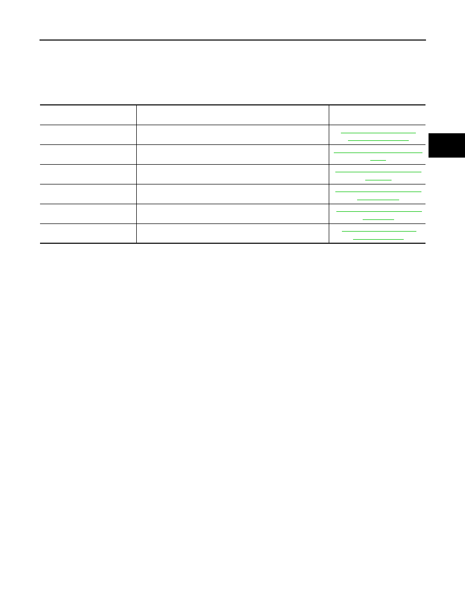
DTC INDEX
C1201-C1210, U1000
INFOID:0000000001534985
DTC
Items
(CONSULT-III screen terms)
Reference
C1201
CONTROLLER FAILURE
C1203
ABS SYSTEM
C1204
4WD SOLENOID
C1205
4WD ACTUATOR RLY
C1210
ENGINE SIGNAL 1
U1000
CAN COMM CIRCUIT