Index Infiniti Infiniti FX35 / FX45 (S50) - service repair manual 2008 year
Search
Content .. 916 917 918 919 ..
Infiniti FX35 / FX45. Manual - part 918
SE-30
< SERVICE INFORMATION >
AUTOMATIC DRIVE POSITIONER
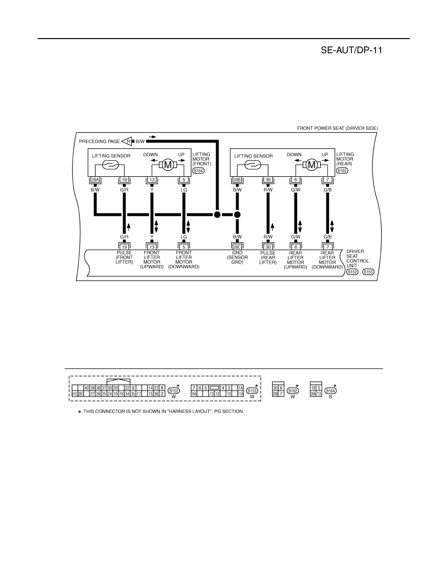
TIWM1703E