Infiniti FX35 / FX45. Manual - part 867


  Index      Infiniti     Infiniti FX35 / FX45 (S50) - service repair manual 2008 year


Search            


Content   ..  865  866  867  868   ..


Infiniti FX35 / FX45. Manual - part 867


PS-10

< SERVICE INFORMATION >

STEERING WHEEL

a.

Disconnect lower joint and steering knuckle from steering gear assembly. Refer to 

PS-12, "Removal and

Installation"

FAX-4, "Removal and Installation"

FAX-11, "Removal and Installation"

.

b.

Start and run engine at idle to make sure steering fluid has reached normal operating temperature.

c.

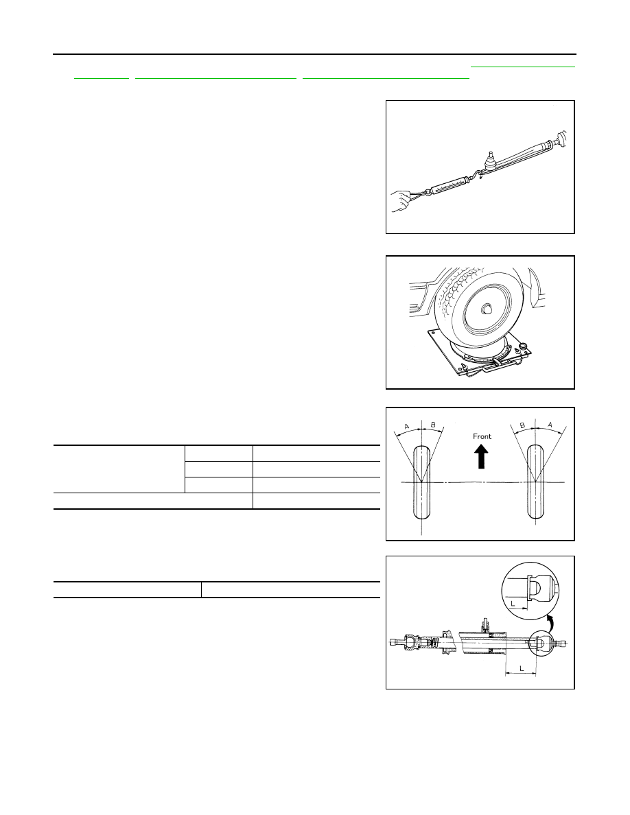
While pulling outer socket slowly in 

±

11.5 mm (

±

0.453 in) range

from neutral position, make sure rack sliding force is within
specification.

d.

If rack sliding force is not within specification, overhaul steering
gear assembly.

CHECKING FRONT WHEEL TURNING ANGLE 

• Check front wheel turning angle after the toe-in inspection. Place

front wheels on turning radius gauges and rear wheels on stands
so that vehicle can be level. Check the maximum inner and outer
wheel turning angles for LH and RH road wheels.

• Start engine and run at idle, turn steering wheel all the way right

and left, measure the turning angle.

• Measure rack stroke if angles are outside the specified value.

• Disassemble steering gear assembly to check the cause that rack

stroke is outside of the standard.

• Steering angles are not adjustable. Check steering gear assembly,

steering column assembly and front suspension components for
wear or damage if any of the turning angles are different from the
specified value. Replace any of them, if any non-standard condi-
tion exists.

Removal and Installation

INFOID:0000000001327713

REMOVAL

NOTE:
When reconnecting spiral cable, fix cable with a tape so that fixing case and rotating part keep aligned. This
will omit neutral position alignment procedure during spiral cable installation.

Rack sliding force

: 147 

 211 N (15 

 21.5 kg, 33 

 47 lb)

SST090B

FAA0016D

Inner wheel (Angle: A)

Minimum

32

°

00’ (32.0

°

)

Nominal

35

°

00’ (35.0

°

)

Maximum

36

°

00’ (36.0

°

)

Outer wheel (Angle: B)

30

°

00’ (30.0

°

)

SGIA0055E

Rack stroke L

67.0 mm (2.638 in)

SGIA0629J

STEERING WHEEL

PS-11

< SERVICE INFORMATION >

C

D

E

F

H

I

J

K

L

M

A

B

PS

N

O

P

1.

Set vehicle to the straight-ahead direction.

2.

Remove driver air bag module. Refer to 

SRS-34, "Removal and Installation"

.

3.

Remove steering wheel lock nut after steering is locked.

4.

Remove steering wheel using the steering wheel puller.

INSTALLATION

Installation is the reverse order of removal. For tightening torque, refer to 

PS-12, "Removal and Installation"

.

NOTE:
Check the spiral cable neutral position after replacing or rotating spiral cable. Refer to 

SRS-36, "Removal and

Installation"

.

CAUTION:

Do not twist spiral cable freely on excessively after it becomes tight (doing so may cause the cable to
be turn off).

Tool number

A: ST27180001 (J-25726-A)

SGIA1323E

PS-12

< SERVICE INFORMATION >

STEERING COLUMN

STEERING COLUMN

Removal and Installation

INFOID:0000000001327714

COMPONENTS

CAUTION:

• Care must be taken not to give axial impact to steering column assembly during removal and instal-

lation.

• Care must be taken not to move steering gear during removal of steering column assembly.

REMOVAL

1.

Set vehicle to the straight ahead-direction.

2.

Remove driver air bag module from steering wheel. Refer to 

SRS-34

.

3.

Disconnect steering switch connector, remove steering wheel lock nut, then remove steering wheel. Refer
to 

SRS-36

.

4.

Remove steering column cover. Refer to 

IP-10

.

5.

Remove combination switch & spiral cable from steering column assembly. Refer to 

SRS-36

.

6.

Remove instrument lower panel (driver side). Refer to 

IP-10

.

7.

Remove combination meter. Refer to 

IP-10

.

1.

Steering wheel

2.

Combination switch & spiral cable

3.

Steering column assembly

4.

Collar

5.

Hole cover seal

6.

Clamp

7.

Hole cover

8.

Lower shaft

9.

Lower joint

Refer to 

GI-8, "Component"

, for the symbols in the figure.

SGIA1612E

STEERING COLUMN

PS-13

< SERVICE INFORMATION >

C

D

E

F

H

I

J

K

L

M

A

B

PS

N

O

P

8.

Remove fixing bolts of knee protector, then remove knee protec-
tor from vehicle.

9.

Disconnect harness connector from each switch on steering col-
umn shaft, then separate vehicle side harness from it.

10. Remove lock nut and bolt, then separate lower shaft from upper

joint of steering column assembly.

11. Remove fixing bolts and nuts from steering member, remove

steering column assembly from steering member.

12. Remove hole cover seal and clamp.
13. Remove mounting nuts, then remove hole cover from panel.

14. Raise vehicle, then remove mounting bolts of lower joint.

15. Remove lower joint and lower shaft from vehicle.

INSPECTION AFTER REMOVAL

• Check if there is something wrong with jacket tube of steering column assembly and collar etc. And then if

they are damaged, replace with new one.

SGIA0552E

SGIA0554E

SGIA0555E

SGIA0557E


Content   ..  865  866  867  868   ..