Infiniti FX35 / FX45. Manual - part 787
DAYTIME LIGHT SYSTEM
LT-43
< SERVICE INFORMATION >
C
D
E
F
G
H
I
J
L
M
A
B
LT
N
O
P
1.
Turn ignition switch OFF.
2.
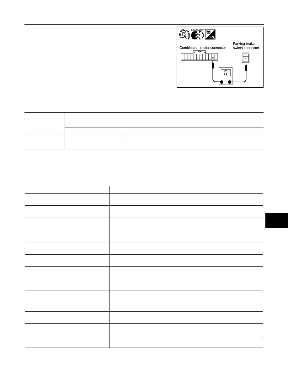
Disconnect combination meter connector.
3.
Check continuity between combination meter harness connector
M20 terminal 23 and parking brake switch harness connector
E207 terminal 1.
OK or NG
OK
>> Replace combination meter.
NG
>> Repair harness or connector.
CONSULT-III Functions (BCM)
INFOID:0000000001328300
CONSULT-III can display each diagnostic item using the diagnostic test mode shown following.
CONSULT-III BASIC OPERATION
.
DATA MONITOR
Display Item List
1 – 23
: Continuity should exist.
SKIA5877E
BCM diagnosis part
Diagnosis mode
Description
HEADLAMP
DATA MONITOR
Displays BCM input data in real time.
ACTIVE TEST
Operation of electrical loads can be checked by sending drive signal to them.
BCM
SELF-DIAG RESULTS
BCM performs self-diagnosis of CAN communication.
CAN DIAG SUPPORT MNTR
The result of transmit/receive diagnosis of CAN communication can be read.
Monitor item
Contents
IGN ON SW
“ON/OFF”
Displays “IGN position (ON)/OFF, ACC position (OFF)” judged from ignition switch sig-
nal.
ACC ON SW
“ON/OFF”
Displays “ACC (ON)/OFF, Ignition OFF (OFF)” status judged from ignition switch sig-
nal.
HI BEAM SW
“ON/OFF”
Displays status (high beam switch: ON/Others: OFF) of high beam switch judged from
lighting switch signal.
HEAD LAMP SW 1
“ON/OFF”
Displays status (headlamp switch 1: ON/Others: OFF) of headlamp switch 1 judged
from lighting switch signal.
HEAD LAMP SW 2
“ON/OFF”
Displays status (headlamp switch 2: ON/Others: OFF) of headlamp switch 2 judged
from lighting switch signal.
LIGHT SW 1 ST
“ON/OFF”
Displays status (lighting switch 1ST or 2ND position: ON/Others: OFF) of lighting
switch judged from lighting switch signal.
AUTO LIGHT SW
NOTE 1
“ON/OFF”
Displays status of lighting switch as judged from lighting switch signal. (AUTO position:
ON/Other than AUTO position: OFF)
PASSING SW
“ON/OFF”
Displays status (flash-to-pass switch: ON/Others: OFF) of flash-to-pass switch judged
from lighting switch signal.
FR FOG SW
“ON/OFF”
Displays status (front fog lamp switch: ON/Others: OFF) of front fog lamp switch
judged from lighting switch signal.
RR FOG SW
NOTE 3
“OFF”
—
DOOR SW - DR
“ON/OFF”
Displays status of driver door as judged from driver door switch signal. (Door is open:
ON/Door is closed: OFF)
DOOR SW - AS
“ON/OFF”
Displays status of passenger door as judged from passenger door switch signal. (Door
is open: ON/Door is closed: OFF)
DOOR SW - RR
“ON/OFF”
Displays status of rear door as judged from rear door switch (RH) signal. (Door is open:
ON/Door is closed: OFF)