Infiniti FX35 / FX45. Manual - part 781
HEADLAMP - XENON TYPE -
LT-19
< SERVICE INFORMATION >
C
D
E
F
G
H
I
J
L
M
A
B
LT
N
O
P
CONSULT-III DATA MONITOR
1.
Select “HL LO REQ” and “HL HI REQ” of IPDM E/R data monitor item.
2.
With operating the lighting switch, check the monitor status
OK or NG
OK
>> Replace IPDM E/R. Refer to
PG-24, "Removal and Installation of IPDM E/R"
.
NG
>> Replace BCM. Refer to
BCS-13, "Removal and Installation of BCM"
.
4.
CHECK HEADLAMP INPUT SIGNAL
CONSULT-III ACTIVE TEST
1.
Turn ignition switch OFF.
2.
Disconnect front combination lamp RH and LH connectors.
3.
Select “LAMPS” of IPDM E/R active test item
4.
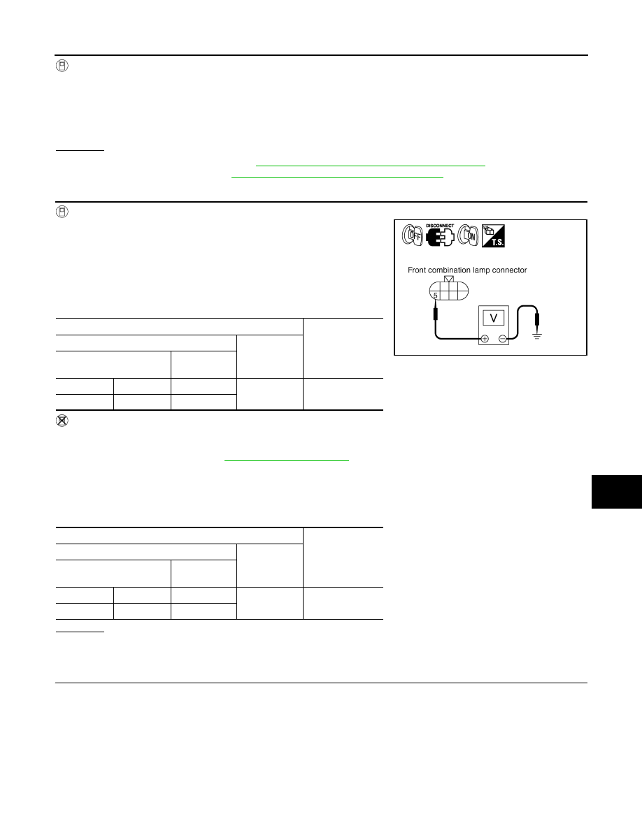
With operating the test item, check voltage between front combi-
nation lamp (RH and LH) harness connectors and ground.
NOTE:
Headlamp high beam repeats ON–OFF every 1 second.
IPDM E/R AUTO ACTIVE TEST
1.
Turn ignition switch OFF.
2.
Disconnect front combination lamp RH and LH connectors.
3.
Start auto active test. Refer to
4.
With operating the test item, check voltage between front combination lamp (RH and LH) harness connec-
tors and ground.
NOTE:
Headlamp high beam repeats ON–OFF every 1 second.
OK or NG
OK
>> GO TO 6.
NG
>> GO TO 5.
5.
CHECK HEADLAMP CIRCUIT
When lighting switch is
HIGH BEAM
: HL LO REQ ON
: HL HI REQ ON
Terminals
Voltage
(Approx.)
(+)
(-)
Front combination lamp
connector
Terminal
RH
E24
5
Ground Battery
voltage
LH
E44
5
Terminals
Voltage
(Approx.)
(+)
(-)
Front combination lamp
connector
Terminal
RH
E24
5
Ground Battery
voltage
LH
E44
5
PKIA5205E