Infiniti FX35 / FX45. Manual - part 766
TROUBLE DIAGNOSIS
LAN-41
< SERVICE INFORMATION >
[CAN]
C
D
E
F
G
H
I
J
L
M
A
B
LAN
N
O
P
0: Error at present, 1 – 39: Error in the past (Number means the number of times the ignition switch is turned OFF
→
ON)
*: 39 or higher number is fixed at 39 until the self-diagnosis result is erased.
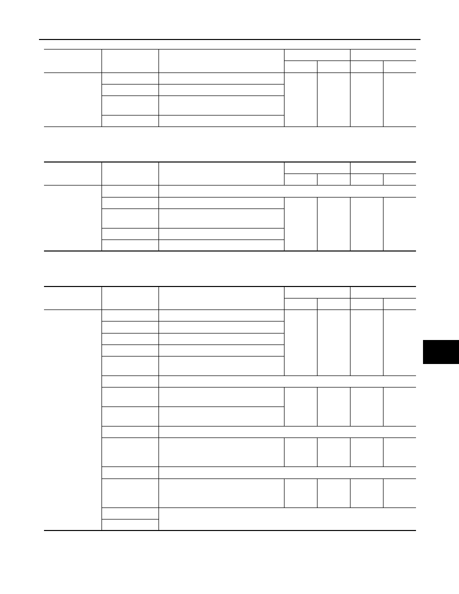
LDW Camera Unit
0: Error at present, 1 – 39: Error in the past (Number means the number of times the ignition switch is turned OFF
→
ON)
*: 39 or higher number is fixed at 39 until the self-diagnosis result is erased.
Unified Meter and A/C Amp.
0: Error at present, 1 – 39: Error in the past (Number means the number of times the ignition switch is turned OFF
→
ON)
*: 39 or higher number is fixed at 39 until the self-diagnosis result is erased.
ABS Actuator and Electric Unit (Control Unit)
ITEM
CAN DIAG SUP-
PORT MNTR
Description
Normal
Error
PRSNT
PAST
PRSNT
PAST
I-KEY
TRANSMIT DIAG
Signal transmission status
OK
OK
or
1 – 39
*
UNKWN
0
ECM
Signal receiving status from the ECM
METER/M&A
Signal receiving status from the unified
meter and A/C amp.
BCM/SEC
Signal receiving status from the BCM
ITEM
CAN DIAG SUP-
PORT MNTR
Description
Normal
Error
PRSNT
PAST
PRSNT
PAST
LKS
TRANSMIT DIAG
Not used even though indicated
ECM
Signal receiving status from the ECM
OK
OK
or
1 – 39
*
UNKWN
0
VDC/TCS/ABS
Signal receiving status from the ABS actu-
ator and electric unit (control unit)
BCM/SEC
Signal receiving status from the BCM
TCM
Signal receiving status from the TCM
ITEM
CAN DIAG SUP-
PORT MNTR
Description
Normal
Error
PRSNT
PAST
PRSNT
PAST
M&A
TRANSMIT DIAG
Signal transmission status
OK
OK
or
1 – 39
*
UNKWN
0
ECM
Signal receiving status from the ECM
TCM
Signal receiving status from the TCM
BCM/SEC
Signal receiving status from the BCM
VDC/TCS/ABS
Signal receiving status from the ABS actu-
ator and electric unit (control unit)
IPDM E/R
Not used even though indicated
DISPLAY
Signal receiving status from the display
control unit
OK
OK
or
1 – 39
*
UNKWN
0
I-KEY
Signal receiving status from the Intelligent
Key unit
EPS
Not used even though indicated
AWD/4WD
Signal receiving status from the AWD con-
trol unit
OK
OK
or
1 – 39
*
UNKWN
0
e4WD
Not used even though indicated
ICC
Signal receiving status from the ICC unit
OK
OK
or
1 – 39
*
UNKWN
0
LANE KEEP
Not used even though indicated
TIRE-P