Infiniti FX35 / FX45. Manual - part 704


  Index      Infiniti     Infiniti FX35 / FX45 (S50) - service repair manual 2008 year


Search            


Content   ..  702  703  704  705   ..


Infiniti FX35 / FX45. Manual - part 704


FFD-26

< SERVICE INFORMATION >

FRONT FINAL DRIVE ASSEMBLY

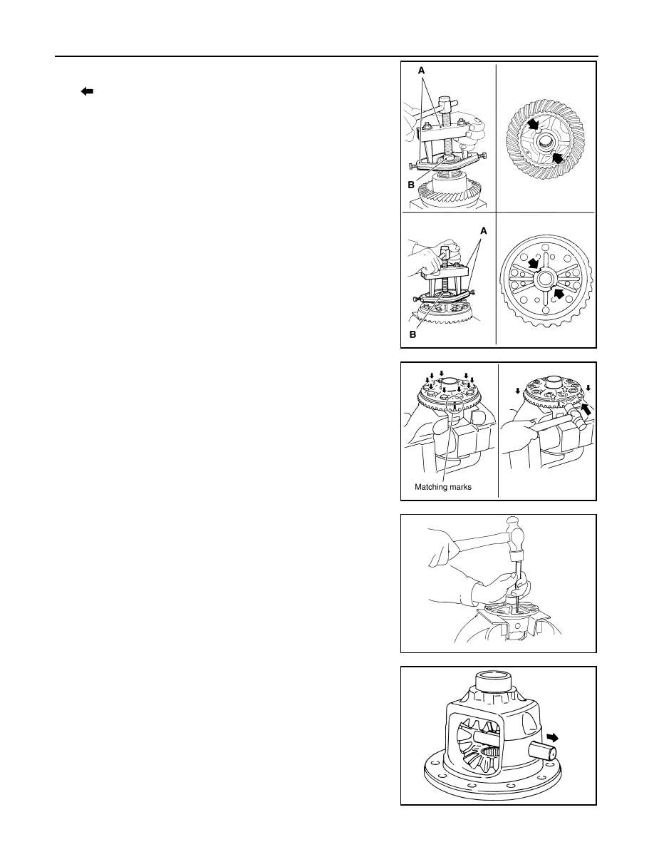
13. Remove side bearing inner race.

To prevent damage to bearing, engage puller jaws in groove
(

).

CAUTION:

• To prevent damage to the side bearing and drive gear,

place copper plates between these parts and vise.

• It is not necessary to remove side bearing inner race

except it is replaced.

14. For proper reinstallation, paint matching marks on one differen-

tial case assembly.

CAUTION:

For matching marks, use paint. Never damage differential
case and drive gear.

15. Remove drive gear mounting bolts.

16. Tap drive gear off differential case assembly with a soft hammer.

CAUTION:

Tap evenly all around to keep drive gear from bending.

17. Remove lock pin of pinion mate shaft with a punch from drive

gear side.

18. Remove pinion mate shaft.

Tool number

 A: ST33051001 (J-22888-20)

 B: ST33061000 (J-8107-2)

PDIA0758J

PDIA0496E

PDIA0759J

SDIA0031J

FRONT FINAL DRIVE ASSEMBLY

FFD-27

< SERVICE INFORMATION >

C

E

F

G

H

I

J

K

L

M

A

B

FFD

N

O

P

19. Turn pinion mate gear, then remove pinion mate gears, pinion

mate thrust washers, side gears and side gear thrust washers
from differential case.

Drive Pinion Assembly

1.

Remove differential assembly. Refer to "Differential Assembly".

2.

Remove drive pinion lock nut with a flange wrench.

3.

Put matching mark (B) on the end of drive pinion. The matching
mark should be in line with the matching mark (A) on companion
flange (1).

CAUTION:

For matching mark, use paint. Never damage companion
flange and drive pinion.
NOTE:
The matching mark (A) on the final drive companion flange (1)
indicates the maximum vertical runout position.
When replacing companion flange, matching mark is not neces-
sary.

4.

Remove companion flange using the suitable puller.

SDIA0032J

PDIA0798J

PDIA0799J

SDIA1132E

FFD-28

< SERVICE INFORMATION >

FRONT FINAL DRIVE ASSEMBLY

5.

Press drive pinion assembly out of gear carrier.

CAUTION:

Never drop drive pinion assembly.

6.

Remove front oil seal.

7.

Remove pinion front bearing inner race.

8.

Remove drive pinion bearing adjusting washer and drive pinion
adjusting washer.

9.

Remove pinion rear bearing inner race and pinion height adjust-
ing washer with replacer.

10. Tap pinion front/rear bearing outer races uniformly a brass rod or

equivalent to removed.

CAUTION:

Be careful not to damage gear carrier.

INSPECTION AFTER DISASSEMBLY

Clean up the disassembled parts. Then, inspect if the parts are worn or damaged. If so, follow the measures
below.

ADJUSTMENT AND SELECTION OF ADJUSTING WASHERS (SHIMS)

PDIA0800J

Tool number

A: ST30031000 (J-22912-01)

PDIA0801J

PDIA0677E

Content

Conditions and Measures

Hypoid gear

• If the gear teeth do not mesh or line-up correctly, determine the cause and adjust or replace as nec-

essary.

• If the gears are worn, cracked, damaged, pitted or chipped (by friction) noticeably, replace with new 

drive gear and drive pinion as a set.

Bearing

• If any chipped (by friction), pitted, worn, rusted or scratched mark, or unusual noise from the bearing 

is observed, replace as a bearing assembly (as a new set).

Side gear and Pinion mate 
gear

• If any cracks or damage on the surface of the tooth is found, replace.
• If any worn or chipped mark on the contact sides of the thrust washer is found, replace.

Side gear thrust washer and 
pinion mate thrust washer

• If it is chipped (by friction), damaged, or unusually worn, replace.

Oil seal 

• Whenever disassembled, replace.
• If wear, deterioration of adherence (sealing force lips), or damage is detected on the lips, replace them.

Differential case

• If any wear or crack on the contact sides of the differential case is found, replace.

Companion flange

• If any chipped mark (about 0.1 mm, 0.004 in) or other damage on the contact sides of the lips of the 

companion flange is found, replace.

FRONT FINAL DRIVE ASSEMBLY

FFD-29

< SERVICE INFORMATION >

C

E

F

G

H

I

J

K

L

M

A

B

FFD

N

O

P

Differential Side Gear Clearance

• Assemble the differential parts if they are disassembled. Refer to "Differential Assembly".

1.

Place differential case straight up so that side gear to be mea-
sured comes upward.

2.

Using feeler gauge, measure the clearance between side gear
back and differential case at 3 different points, while rotating
side gear. Average the 3 readings, and then measure the clear-
ance of the other side as well.

CAUTION:

To prevent side gear from tilting, insert feeler gauges with
the same thickness from both sides.

3.

If the back clearance is outside the specification, use a thicker/
thinner side gear thrust washer to adjust. Refer to 

FFD-39,

"Inspection and Adjustment"

.

CAUTION:

Select a side gear thrust washer for right and left individually.

Side Bearing Preload

1.

Make sure all parts are clean. Also, make sure the bearings are well lubricated with gear oil.

2.

Press-fit side bearing outer race into side retainer with tool.

CAUTION:

• At first, using a hammer, tap bearing outer race until it

becomes flat to side retainer.

• Never reuse side bearing outer race.

PDIA0460E

Side gear back clearance specification:

0.2 mm (0.008 in) or less.
(Each gear should rotate smoothly without excessive 
resistance during differential motion.)

When the back clearance is large:

Use a thicker thrust washer.

When the back clearance is small:

Use a thinner thrust washer.

PDIA0576E

Tool number

A: ST30611000 (J-25742-1)

B: KV31103000 (J-38982)

PDIA0811J


Content   ..  702  703  704  705   ..