Infiniti FX35 / FX45. Manual - part 697
FAX-24
< SERVICE INFORMATION >
[AWD]
FRONT DRIVE SHAFT
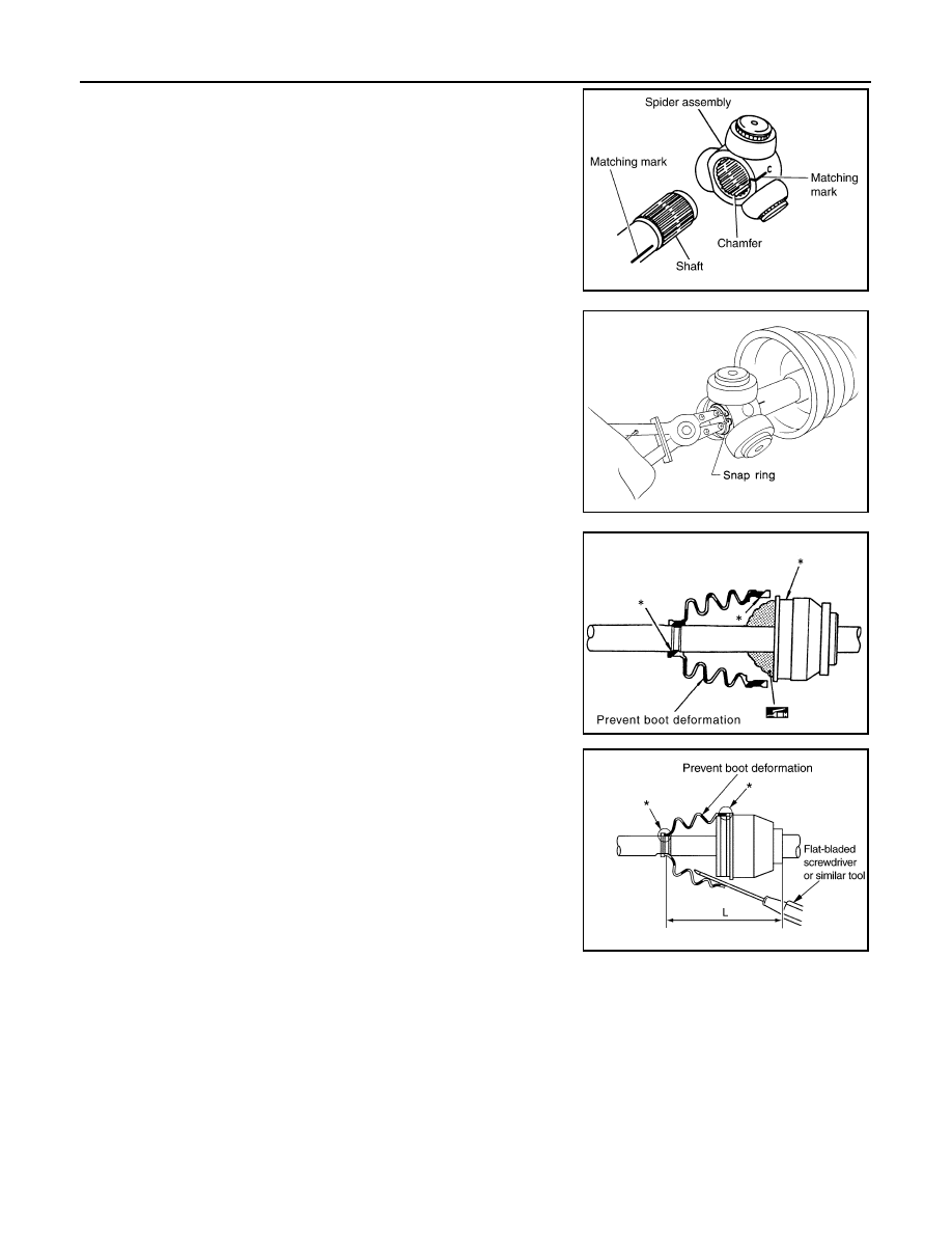
3.
Line up alignment marks which were made when spider assem-
bly was removed. Install spider assembly, with serration chamfer
facing dive shaft.
4.
Secure spider assembly with snap ring.
NOTE:
Discard old snap ring; replace with new one.
5.
Apply Nissan genuine grease or equivalent to spider assembly
and sliding surface.
6.
Install housing to spider assembly. Apply Nissan genuine grease
or equivalent to housing.
7.
Install boot securely into grooves (indicated by * marks) shown
in the figure.
CAUTION:
If there is grease on boot mounting surfaces (indicated by*
marks) of shaft and housing, boot may come off. Remove
all grease from surfaces.
8.
Make sure boot installation length “L” is the length indicated
below. Insert a flat-bladed screwdriver or similar tool into smaller
side of boot. Bleed air from boot to prevent boot deformation.
CAUTION:
• Boot may break if boot installation length is less than standard value.
• Take care not to touch the tip of screwdriver to inside surface of boot.
9.
Install new larger and smaller boot bands securely.
NOTE:
Discard old boot bands; replace with new ones.
SDIA2629E
SFA023A
Grease amount
: 113
−
123 g (3.98
−
4.33 oz)
SDIA1446E
Boot installation Length “L”:
157.55
−
159.55 mm (6.20
−
6.28 in)
SDIA3250E