Infiniti FX35 / FX45. Manual - part 694


  Index      Infiniti     Infiniti FX35 / FX45 (S50) - service repair manual 2008 year


Search            


Content   ..  692  693  694  695   ..


Infiniti FX35 / FX45. Manual - part 694


FAX-12

< SERVICE INFORMATION >

[AWD]

FRONT WHEEL HUB AND KNUCKLE

5.

Remove cotter pin, then remove lock nut from drive shaft.

6.

Remove steering outer socket and cotter pin at steering knuckle, then loosen mounting nut.

7.

Use a ball joint remover (SST) to remove steering outer socket
from steering knuckle. Be careful not to damage ball joint boot.

CAUTION:

To prevent damage to threads and to prevent ball joint
remover (SST) from coming off suddenly, temporarily
tighten mounting nut. 

8.

Using a puller (suitable tool), remove wheel hub and bearing assembly from drive shaft.
NOTE:
• When removing wheel hub and bearing assembly, do not apply an excessive angle to drive shaft joint.

Also be careful not to excessively extend slide joint.

• Do not hang over drive shaft with out support.

9.

Remove wheel hub and bearing assembly fixing bolt.

10. Remove splash guard and wheel hub and bearing assembly from steering knuckle.

11. Remove strut assembly and steering knuckle fixing bolts and nuts.
12. Remove transverse link and steering knuckle fixing bolt and nut.

13. Remove steering knuckle from vehicle.

INSPECTION AFTER REMOVAL

Check for deformity, cracks and damage on each parts, replace if necessary.

Ball Joint Inspection

Check for boot breakage, axial looseness, and torque of transverse link and steering outer socket ball joint.
Refer to 

FSU-13

PS-17

.

INSTALLATION

CAUTION:

Be sure to replace the new differential side oil seal every removal of drive shaft. Refer to 

FFD-12

.

• Refer to "Removal and Installation"for tightening torque. Install in the reverse order of removal.

NOTE:
Refer to component parts location and do not reuse non-reusable parts.

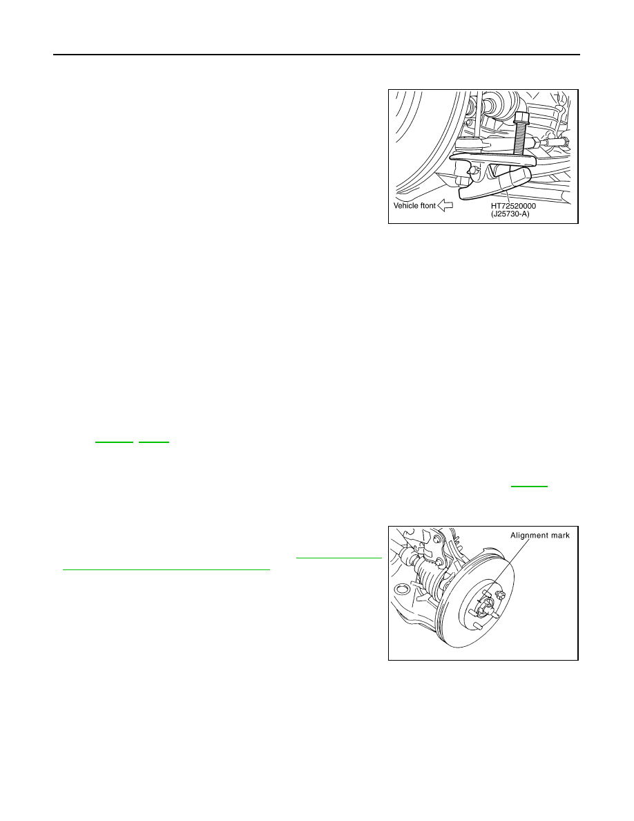
• To assemble disc rotor and wheel hub and bearing assembly, align

the marks.
(When not using the alignment mark, refer to 

BR-19, "Removal

and Installation of Brake Caliper Assembly"

.)

SGIA0488E

SDIA1480E

FRONT DRIVE SHAFT

FAX-13

< SERVICE INFORMATION >

[AWD]

C

E

F

G

H

I

J

K

L

M

A

B

FAX

N

O

P

FRONT DRIVE SHAFT

On-Vehicle Inspection

INFOID:0000000001327515

• Check drive shaft mounting point and joint for looseness and other damage.
• Check boot for cracks and other damage.

CAUTION:

Replace entire drive shaft assembly when noise or vibration occur from drive shaft.

DRIVE SHAFT BOOT REPLACEMENT

1.

Remove tires from vehicle with power tool.

2.

Remove undercover with power tool.

3.

Remove cotter pin. Then remove lock nut from drive shaft with power tool.

4.

Remove wheel sensor harness from strut assembly. Refer to 

BRC-52

.

CAUTION:

Do not pull on wheel sensor harness.

5.

Remove brake hose lock plate. Then remove brake hose from strut assembly. Refer to 

BR-10

.

6.

Remove fixing bolts and nuts between strut assembly and steering knuckle with power tool. 

7.

Remove drive shaft from wheel hub and bearing assembly.

8.

Using a puller (suitable tool), remove drive shaft from steering
knuckle.

CAUTION:

When removing drive shaft, do not apply an excessive
angle to drive shaft joint. Also be careful not to excessively
extend slide joint.

9.

Remove boot bands, and then remove boot from joint sub-assembly.

10. Screw a drive shaft puller (suitable tool) into joint sub-assembly

screw part to a length of 30 mm (1.18 in) or more. Support drive
shaft with one hand and pull out joint sub-assembly with a slid-
ing hammer (suitable tool) from shaft.

CAUTION:

• Align a sliding hammer and drive shaft and remove them

by pulling firmly and uniformly.

• If joint sub-assembly cannot be pulled out, try after

removing drive shaft from vehicle.

11. Remove the circular clip from shaft.

12. Remove boot from shaft.

13. Clean the old grease on joint sub-assembly with paper towels.

SDIA0972J

SDIA0881J

SDIA2489E

FAX-14

< SERVICE INFORMATION >

[AWD]

FRONT DRIVE SHAFT

14. Apply the specified amount of grease (NISSAN genuine grease

or equivalent) inside joint sub-assembly serration hole until
grease begins to ooze from ball groove and serration hole. After
applying grease, use a shop cloth to wipe off old grease that has
oozed out.

15. Wrap serration on shaft with tape to protect the boot from dam-

age. Install new boot and boot bands to shaft.

16. Remove the tape wrapped around the serration on shaft.

17. Position circular clip on groove at the shaft edge. Align both

counter axles of the shaft edge and joint sub-assembly. Then,
assemble shaft with circular clip onto joint sub-assembly.
NOTE:
Drive joint inserter (suitable tool) is recommended when install-
ing circular clip.

18. Install joint sub-assembly to shaft using plastic hammer.

CAUTION:

Confirm that joint sub-assembly is correctly engaged while
rotating drive shaft.

19. Apply the balance of the specified amount of grease (NISSAN

genuine grease or equivalent) into the boot inside from large
diameter side of boot.

20. Install the boot securely into grooves (indicated by *marks)

shown in the figure.

CAUTION:

If grease adheres to the boot mounting surface (with *mark)
on the shaft and joint sub-assembly, boot may come off.
Remove all grease from the surface.

21. To prevent from the deformation of the boot, adjust the boot

installation length to the specified value shown below (L) by
inserting the flat-bladed screwdriver into inside of the boot from
the large diameter side of the boot and discharging the inside
air.

SDIA2775E

SFA800

SDIA2490E

Grease amount

: 77 – 97 g (2.71 – 3.42 oz)

SDIA2372E

SDIA1760E

FRONT DRIVE SHAFT

FAX-15

< SERVICE INFORMATION >

[AWD]

C

E

F

G

H

I

J

K

L

M

A

B

FAX

N

O

P

CAUTION:

• If the boot mounting length is outside the standard, it may cause breakage in the boot.
• Be careful not to touch the inside of the boot with a tip of a flat-bladed screwdriver.

22. Secure the large and small ends of the boot with new boot

bands using the boot band crimping tool [SST: KV40107300
(

)] as shown in the figure.

NOTE:
Secure boot band so that dimension “M” meets the specification
as shown.

23. Secure joint sub-assembly and shaft, and then make sure that

they are in the correct position when rotating boot. Install them
with new boot band when boot installation positions become
incorrect.

24. Insert drive shaft to wheel hub and bearing assembly, and then

temporarily tighten hub lock nut.

25. Install nuts and bolts to steering knuckle and strut.

26. Install break hose bracket to strut assembly.

BR-10, "Removal and Installation of Front Brake Tube and

Brake Hose"

27. Install wheel sensor to strut assembly. Refer to  

BRC-52

.

28. Tighten the hub lock nut to the specified torque.
29. Install cotter pin.

30. Install tires to vehicle.

Removal and Installation (Left Side)

INFOID:0000000001327516

COMPONENTS

REMOVAL

1.

Remove tires from vehicle with power tool.

Boot installation length (L)

: 136 mm (5.35 in)

RAC1133D

Dimension “M”

: 2.0 – 3.0 mm (0.079 – 0.118 in)

DSF0047D

1.

Cotter pin

2.

Washer

3.

Drive shaft

Refer to 

GI-8, "Component"

, for the symbols in the figure.

PDIA1218E


Content   ..  692  693  694  695   ..