Infiniti FX35 / FX45. Manual - part 668
SPARK PLUG (PLATINUM-TIPPED TYPE)
EM-189
< SERVICE INFORMATION >
[VK45DE]
C
D
E
F
G
H
I
J
K
L
M
A
EM
N
P
O
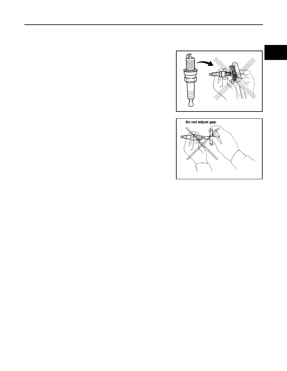
CAUTION:
• Do not drop or shock spark plug.
• Do not use wire brush for cleaning.
• If plug tip is covered with carbon, spark plug cleaner may be
used.
• Checking and adjusting plug gap is not required between
change intervals.
INSTALLATION
Install in the reverse order of removal.
Gap (Nominal)
: 1.1 mm (0.043 in)
Cleaner air pressure:
Less than 588 kPa (6 kg/cm
2
, 85 psi)
Cleaning time:
Less than 20 seconds
SMA773C
SMA806CA