Infiniti FX35 / FX45. Manual - part 657


  Index      Infiniti     Infiniti FX35 / FX45 (S50) - service repair manual 2008 year


Search            


Content   ..  655  656  657  658   ..


Infiniti FX35 / FX45. Manual - part 657


CYLINDER BLOCK

EM-145

< SERVICE INFORMATION >

[VQ35DE]

C

D

E

F

G

H

I

J

K

L

M

A

EM

N

P

O

• Measure the outer diameter of crankshaft pin journal with a

micrometer.

• If out of the standard, measure the connecting rod bearing oil

clearance. Then use undersize bearing. Refer to "CONNECTING
ROD BEARING OIL CLEARANCE".

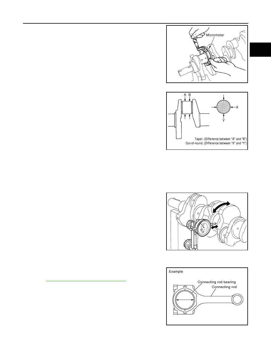
CRANKSHAFT OUT-OF-ROUND AND TAPER

• Measure the dimensions at four different points as shown in the

figure on each main journal and pin journal with a micrometer. 

• Out-of-round is indicated by the difference in the dimensions

between “X” and “Y” at “A” and “B”.

• Taper is indicated by the difference in the dimensions between “A”

and “B” at “X” and “Y”.

• If the measured value exceeds the limit, correct or replace crankshaft.
• If corrected, measure the bearing oil clearance of the corrected main journal and/or pin journal. Then select

the main bearing and/or connecting rod bearing. Refer to "MAIN BEARING OIL CLEARANCE" and/or
"CONNECTING ROD BEARING OIL CLEARANCE".

CRANKSHAFT RUNOUT 

• Place V-block on precise flat table, and support the journals on the

both end of crankshaft.

• Place a dial indicator straight up on the No. 3 journal.
• While rotating crankshaft, read the movement of the pointer on a

dial indicator. (Total indicator reading)

• If it exceeds the limit, replace crankshaft.

CONNECTING ROD BEARING OIL CLEARANCE

Method by Calculation

• Install connecting rod bearings to connecting rod and connecting

rod cap, and tighten connecting rod bolts to the specified torque.
Refer to 

EM-123, "Disassembly and Assembly"

 for the tightening

procedure.

• Measure the inner diameter of connecting rod bearing with an

inside micrometer.

(Oil clearance) = (Connecting rod bearing inner diameter) – (Crank-
shaft pin journal diameter)

Standard

: 51.956 - 51.974 mm (2.0455 - 2.0462 in) dia.

PBIC0127E

Limit:

Out-of-round (Difference between “X” and “Y”)

: 0.002 mm (0.0001 in)

Taper (Difference between “A” and “B”)

: 0.002 mm (0.0001 in)

SBIA0535E

Standard

: Less than 0.05 mm (0.0020 in)

Limit

: 0.10 mm (0.0039 in)

SEM346D

Standard

:

0.034 - 0.059 mm (0.0013 - 0.0023 in)
(actual clearance)

Limit

:

0.070 mm (0.0028 in)

PBIC1642E

EM-146

< SERVICE INFORMATION >

[VQ35DE]

CYLINDER BLOCK

• If the calculated value exceeds the limit, select proper connecting rod bearing according to connecting rod

big end diameter and crankshaft pin journal diameter to obtain the specified bearing oil clearance. Refer to

EM-134, "How to Select Piston and Bearing"

.

Method of Using Plastigage

• Remove oil and dust on crankshaft pin journal and the surfaces of each bearing completely. 
• Cut a plastigage slightly shorter than the bearing width, and place it in crankshaft axial direction, avoiding oil

holes.

• Install connecting rod bearings to connecting rod and connecting rod bearing cap, and tighten connecting

rod bolts to the specified torque. Refer to 

EM-123, "Disassembly and Assembly"

 for the tightening proce-

dure.

CAUTION:

Do not rotate crankshaft.

• Remove connecting rod bearing cap and bearings, and using the

scale on the plastigage bag, measure the plastigage width.
NOTE:
The procedure when the measured value exceeds the limit is
same as that described in the “Method by Calculation”.

MAIN BEARING OIL CLEARANCE

Method by Calculation

• Install main bearings to cylinder block and main bearing caps, and

tighten main bearing cap bolts with main bearing beam to the
specified torque. Refer to 

EM-123, "Disassembly and Assembly"

for the tightening procedure.

• Measure the inner diameter of main bearing with a bore gauge.
(Oil clearance) = (Main bearing inner diameter) – (Crankshaft main
journal diameter)

• If the calculated value exceeds the limit, select proper main bearing according to main bearing inner diame-

ter and crankshaft main journal diameter to obtain the specified bearing oil clearance. Refer to 

EM-134,

"How to Select Piston and Bearing"

.

Method of Using Plastigage

• Remove engine oil and dust on crankshaft journal and the surfaces of each bearing completely. 
• Cut a plastigage slightly shorter than the bearing width, and place it in crankshaft axial direction, avoiding oil

holes.

• Install main bearing to cylinder block and main bearing cap, and tighten main bearing bolts with main bear-

ing beam to the specified torque. Refer to 

EM-123, "Disassembly and Assembly"

 for the tightening proce-

dure.

CAUTION:

Never rotate crankshaft.

PBIC1149E

Standard

:

0.035 - 0.045 mm (0.0014 - 0.0018 in)
(actual clearance)

Limit

:

0.065 mm (0.0026 in)

PBIC1644E

CYLINDER BLOCK

EM-147

< SERVICE INFORMATION >

[VQ35DE]

C

D

E

F

G

H

I

J

K

L

M

A

EM

N

P

O

• Remove main bearing caps and bearings, and using the scale on

the plastigage bag, measure the plastigage width. 
NOTE:
The procedure when the measured value exceeds the limit is
same as that described in the “Method by Calculation”.

MAIN BEARING CRUSH HEIGHT

• When main bearing cap is removed after being tightened to the

specified torque with main bearings installed, the tip end of bearing
must protrude. Refer to 

EM-123, "Disassembly and Assembly"

 for

the tightening procedure.

• If the standard is not met, replace main bearings.

CONNECTING ROD BEARING CRUSH HEIGHT

• When connecting rod bearing cap is removed after being tightened

to the specified torque with connecting rod bearings installed, the
tip end of bearing must protrude. Refer to 

EM-123, "Disassembly

and Assembly"

 for the tightening procedure.

• If the standard is not met, replace connecting rod bearings.

MAIN BEARING CAP BOLT OUTER DIAMETER

• Measure the outer diameters (“d

1

”, “d

2

”) at two positions as shown

in the figure.

• If reduction appears in “A” range, regard it as “d

2

”.

• If it exceeds the limit (large difference in dimensions), replace main

bearing cap bolt with new one.

CONNECTING ROD BOLT OUTER DIAMETER

PBIC1149E

Standard

: There must be crush height.

SEM502G

Standard

: There must be crush height.

PBIC1646E

Limit (“d

1

” – “d

2

”)

: 0.11 mm (0.0043 in)

PBIC0911E

EM-148

< SERVICE INFORMATION >

[VQ35DE]

CYLINDER BLOCK

• Measure the outer diameter “d” at position shown in the figure.
• If the reduction appears in a position other than “d”, regard it as “d”.

• When “d” exceeds the limit (when it becomes thinner), replace

connecting rod bolt with new one.

DRIVE PLATE

• Check drive plate and signal plate for deformation or damage.

CAUTION:

• Do not disassemble drive plate.
• Do not place drive plate with signal plate facing down.
• When handling signal plate, take care not to damage or

scratch it. 

• Handle signal plate in a manner that prevents it from becom-

ing magnetized.

• If anything is found, replace drive plate.

OIL JET

• Check nozzle for deformation and damage.
• Blow compressed air from nozzle, and check for clogs.
• If it is not satisfied, clean or replace oil jet.

OIL JET RELIEF VALVE

• Using a clean plastic stick, press check valve in oil jet relief valve.

Make sure that valve moves smoothly with proper reaction force.

• If it is not satisfied, replace oil jet relief valve.

Standard

: 7.90 - 8.00 mm (0.3110 - 0.3150 in)

Limit

: 7.75 mm (0.3051 in)

PBIC0912E

SEM760G

EMU0468D


Content   ..  655  656  657  658   ..