Infiniti FX35 / FX45. Manual - part 642


  Index      Infiniti     Infiniti FX35 / FX45 (S50) - service repair manual 2008 year


Search            


Content   ..  640  641  642  643   ..


Infiniti FX35 / FX45. Manual - part 642


CAMSHAFT

EM-85

< SERVICE INFORMATION >

[VQ35DE]

C

D

E

F

G

H

I

J

K

L

M

A

EM

N

P

O

6.

Remove valve lifter.
• Identify installation positions, and store them without mixing them up.

7.

Remove timing chain tensioner (secondary) from cylinder head.
• Remove timing chain tensioner (secondary) with its stopper

pin attached.

NOTE:
Stopper pin was attached when timing chain (secondary) was
removed.

INSPECTION AFTER REMOVAL

Camshaft Runout

1.

Put V-block on precise flat table, and support No. 2 and 4 jour-
nals of camshaft.

CAUTION:

Do not support No. 1 journal (on the side of camshaft
sprocket) because it has a different diameter from the other
three locations.

2.

Set a dial indicator vertically to No. 3 journal.

3.

Turn camshaft to one direction with hands, and measure the
camshaft runout on a dial indicator. (Total indicator reading)

4.

If it exceeds the limit, replace camshaft.

Camshaft Cam Height

1.

Measure the camshaft cam height with a micrometer.

2.

If wear exceeds the limit, replace camshaft.

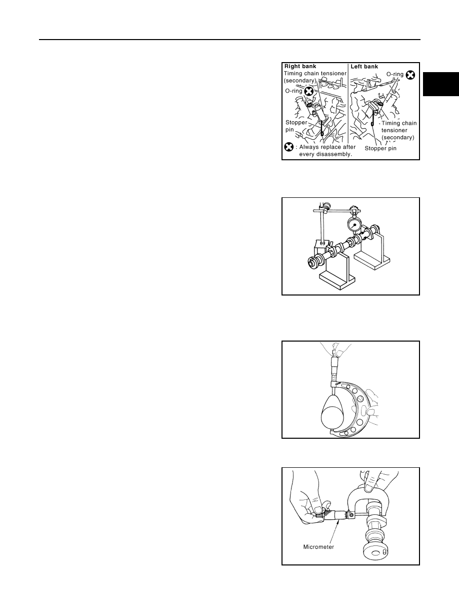
Camshaft Journal Oil Clearance

CAMSHAFT JOURNAL DIAMETER

• Measure the outer diameter of camshaft journal with a micrometer.

PBIC2111E

Standard

: Less than 0.02 mm (0.0008 in)

Limit

: 0.05 mm (0.0020 in)

PBIC0929E

Standard cam height (intake and exhaust)

: 44.865 - 45.055 mm (1.7663 - 1.7738 in)

Cam wear limit

: 0.2 mm (0.008 in)

EMQ0072D

Standard:

No. 1

: 25.935 - 25.955 mm (1.0211 - 1.0218 in)

No. 2, 3, 4

: 23.445 - 23.465 mm (0.9230 - 0.9238 in)

PBIC0040E

EM-86

< SERVICE INFORMATION >

[VQ35DE]

CAMSHAFT

CAMSHAFT BRACKET INNER DIAMETER 

• Tighten camshaft bracket bolt with the specified torque. Refer to "INSTALLATION" for the tightening proce-

dure.

• Measure inner diameter “A” of camshaft bracket with a bore gauge.

CAMSHAFT JOURNAL OIL CLEARANCE

• (Oil clearance) = (Camshaft bracket inner diameter) – (Camshaft journal diameter).

• If the calculated value exceeds the limit, replace either or both camshaft and cylinder head.

NOTE:
Camshaft brackets cannot be replaced as single parts, because there are machined together with cylinder
head. Replace whole cylinder head assembly.

Camshaft End Play

• Install a dial indicator in thrust direction on front end of camshaft.

Measure the end play of a dial indicator when camshaft is moved
forward/backward (in direction to axis).

• Measure the following parts if out of the limit.
- Dimension “A” for camshaft No. 1 journal

- Dimension “B” for cylinder head No. 1 journal bearing

• Refer to the standards above, and then replace camshaft and/or

cylinder head.

Camshaft Sprocket Runout

1.

Put V-block on precise flat table, and support No. 2 and 4 journals of camshaft.

CAUTION:

Do not support No. 1 journal (on the side of camshaft sprocket) because it has a different diameter
from the other three locations.

Standard:

No. 1

: 26.000 - 26.021 mm (1.0236 - 1.0244 in)

No. 2, 3, 4

: 23.500 - 23.521 mm (0.9252 - 0.9260 in)

PBIC1645E

Standard:

No. 1

: 0.045 - 0.086 mm (0.0018 - 0.0034 in)

No. 2, 3, 4

: 0.035 - 0.076 mm (0.0014 - 0.0030 in)

Limit

: 0.15 mm (0.0059 in)

Standard

: 0.115 - 0.188 mm (0.0045 - 0.0074 in)

Limit

: 0.24 mm (0.0094 in)

SEM864E

Standard

: 27.500 - 27.548 mm (1.0827 - 1.0846 in)

Standard

: 27.360 - 27.385 mm (1.0772 - 1.0781 in)

KBIA2404J

CAMSHAFT

EM-87

< SERVICE INFORMATION >

[VQ35DE]

C

D

E

F

G

H

I

J

K

L

M

A

EM

N

P

O

2.

Measure the camshaft sprocket runout with a dial indicator.
(Total indicator reading)

• If it exceeds the limit, replace camshaft sprocket.

Valve Lifter 

Check if surface of valve lifter has any wear or cracks.
• If anything above is found, replace valve lifter. Refer to 

EM-149,

"Standard and Limit"

.

Valve Lifter Clearance

VALVE LIFTER OUTER DIAMETER

• Measure the outer diameter at 1/2 height of valve lifter with a

micrometer since valve lifter is in barrel shape.

VALVE LIFTER HOLE DIAMETER

• Measure the inner diameter of valve lifter hole of cylinder head with

an inside micrometer.

VALVE LIFTER CLEARANCE

• (Valve lifter clearance) = (Valve lifter hole diameter) – (Valve lifter outer diameter)

Limit

: 0.15 mm (0.0059 in)

PBIC0930E

KBIA0182E

Standard

Identification (stamped) mark “R” or “U”

: 33.977 - 33.987 mm (1.3377 - 1.3381 in)

Identification (stamped) mark “V”

: 33.980 - 33.990 mm (1.3378 - 1.3382 in)

JEM798G

Standard (Intake and exhaust)

: 34.000 - 34.016 mm (1.3386 - 1.3392 in)

SEM867E

Standard

Identification (stamped) mark “R” or “U”

: 0.013 - 0.039 mm (0.0005 - 0.0015 in)

EM-88

< SERVICE INFORMATION >

[VQ35DE]

CAMSHAFT

• If the calculated value is out of the standard, referring to each standard of valve lifter outer diameter and

valve lifter hole diameter, replace either or both valve lifter and cylinder head.

INSTALLATION

1.

Install timing chain tensioners (secondary) on both sides of cyl-
inder head.
• Install timing chain tensioner with its stopper pin attached. 
• Install timing chain tensioner with sliding part facing downward

on right-side cylinder head, and with sliding part facing upward
on left-side cylinder head.

• Install new O-ring as shown in the figure.

2.

Install valve lifter.
• Install it in the original position.

3.

Install camshafts.
• Install camshaft with dowel pin attached to its front end face on

the exhaust side.

• Follow your identification marks made during removal, or fol-

low the identification marks that are present on new camshafts
for proper placement and direction.

• Install camshaft so that dowel pin hole and dowel pin on front

end face are positioned as shown in the figure. (No. 1 cylinder
TDC on its compression stroke)
NOTE:
• Large and small pin holes are located on front end face of

camshaft (INT), at intervals of 180 degrees. Face small dia.
side pin hole upward (in cylinder head upper face direction).

• Though camshaft does not stop at the portion as shown in

the figure, for the placement of cam nose, it is generally
accepted camshaft is placed for the same direction of the fig-
ure.

Identification (stamped) mark “V”

: 0.010 - 0.036 mm (0.0004 - 0.0014 in)

PBIC2111E

KBIA1071E

Bank

INT/EXH

Dowel pin

Paint marks

Identification 

mark

M1

M2

RH

EXH

Yes

No

Orange

RE

INT

No

Pink

No

RE

LH

INT

No

Pink

No

LH

EXH

Yes

No

Orange

LH

KBIA1009E

PBIC2478E


Content   ..  640  641  642  643   ..