Infiniti FX35 / FX45. Manual - part 603
IGNITION SIGNAL
EC-1173
< SERVICE INFORMATION >
[VK45DE]
C
D
E
F
G
H
I
J
K
L
M
A
EC
N
P
O
OK
>> INSPECTION END
NG
>> GO TO 10.
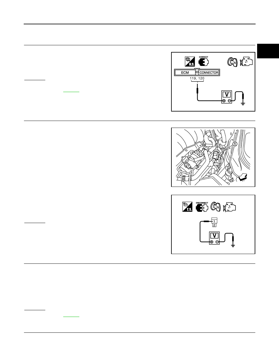
4.
CHECK IGNITION COIL POWER SUPPLY CIRCUIT-I
1.
Turn ignition switch OFF, wait at least 10 seconds and then turn ON.
2.
Check voltage between ECM terminals 119, 120 and ground
with CONSULT-III or tester.
OK or NG
OK
>> GO TO 5.
NG
>> Go to
.
5.
CHECK IGNITION COIL POWER SUPPLY CIRCUIT-II
1.
Turn ignition switch OFF.
2.
Disconnect condenser (1) harness connector.
-
Vehicle front
3.
Turn ignition switch ON.
4.
Check voltage between condenser terminal 1 and ground with
CONSULT-III or tester.
OK or NG
OK
>> GO TO 8.
NG
>> GO TO 6.
6.
CHECK IGNITION COIL POWER SUPPLY CIRCUIT-III
1.
Turn ignition switch OFF.
2.
Disconnect IPDM E/R harness connector E7.
3.
Check harness continuity between IPDM E/R terminal 17 and condenser terminal 1.
Refer to Wiring Diagram.
4.
Also check harness for short to ground and short to power.
OK or NG
OK
>> Go to
.
NG
>> GO TO 7.
7.
DETECT MALFUNCTIONING PART
Check the following.
• Harness connectors E19, F49
Voltage: Battery voltage
MBIB0034E
PBIB3233E
Voltage: Battery voltage
PBIB0624E
Continuity should exist.