Infiniti FX35 / FX45. Manual - part 599
FUEL PUMP
EC-1157
< SERVICE INFORMATION >
[VK45DE]
C
D
E
F
G
H
I
J
K
L
M
A
EC
N
P
O
Diagnosis Procedure
INFOID:0000000001327060
1.
CHECK OVERALL FUNCTION
1.
Turn ignition switch ON.
2.
Pinch fuel feed hose (1) with two fingers.
OK or NG
OK
>> INSPECTION END
NG
>> GO TO 2.
2.
CHECK FUEL PUMP POWER SUPPLY CIRCUIT-I
1.
Turn ignition switch OFF.
2.
Disconnect ECM harness connector.
3.
Turn ignition switch ON.
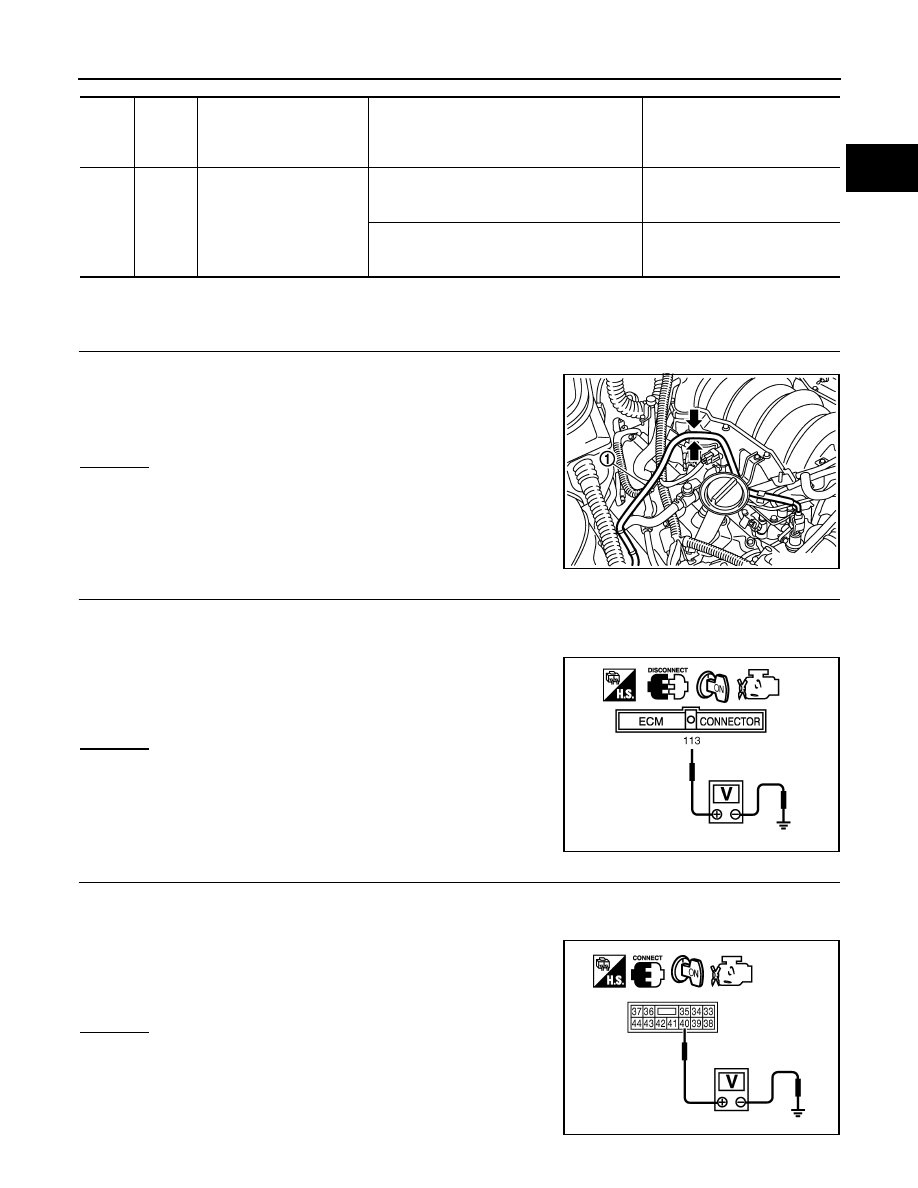
4.
Check voltage between ECM terminal 113 and ground with
CONSULT-III or tester.
OK or NG
OK
>> GO TO 5.
NG
>> GO TO 3.
3.
CHECK FUEL PUMP POWER SUPPLY CIRCUIT-II
1.
Turn ignition switch OFF.
2.
Disconnect IPDM E/R harness connector E8.
3.
Turn ignition switch ON.
4.
Check voltage between IPDM E/R terminal 40 and ground with
CONSULT-III or tester.
OK or NG
OK
>> GO TO 4.
NG
>> GO TO 11.
TER-
MI-
NAL
NO.
WIRE
COLOR
ITEM
CONDITION
DATA (DC Voltage)
113
GY/R
Fuel pump relay
[Ignition switch: ON]
• For 1 second after turning ignition switch ON
[Engine is running]
0 - 1.5V
[Ignition switch: ON]
• More than 1 second after turning ignition
switch ON
BATTERY VOLTAGE
(11 - 14V)
Fuel pressure pulsation should be felt on the fuel feed
hose for 1 second after ignition switch is turned ON.
PBIB3245E
Voltage: Battery voltage
PBIB1187E
Voltage: Battery voltage
PBIB1926E