Infiniti FX35 / FX45. Manual - part 595
ASCD BRAKE SWITCH
EC-1141
< SERVICE INFORMATION >
[VK45DE]
C
D
E
F
G
H
I
J
K
L
M
A
EC
N
P
O
Diagnosis Procedure
INFOID:0000000001327042
1.
CHECK OVERALL FUNCTION-I
With CONSULT-III
1.
Turn ignition switch ON.
2.
Select “BRAKE SW1” in “DATA MONITOR” mode with CONSULT-III.
3.
Check “BRAKE SW1” indication under the following conditions.
Without CONSULT-III
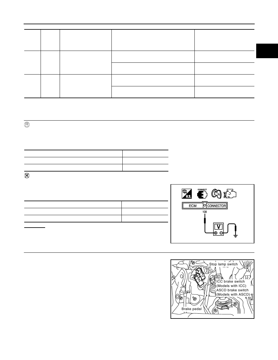
1.
Turn ignition switch ON.
2.
Check voltage between ECM terminal 108 and ground under the
following conditions.
OK or NG
OK
>> INSPECTION END
NG
>> GO TO 2.
2.
CHECK ASCD BRAKE SWITCH POWER SUPPLY CIRCUIT
1.
Turn ignition switch OFF.
2.
Disconnect ASCD brake switch harness connector.
3.
Turn ignition switch ON.
TER-
MI-
NAL
NO.
WIRE
COLOR
ITEM
CONDITION
DATA (DC Voltage)
101
P/L
Stop lamp switch
[Ignition switch: OFF]
• Brake pedal: Fully released
Approximately 0V
[Ignition switch: OFF]
• Brake pedal: Slightly depressed
BATTERY VOLTAGE
(11 - 14V)
108
SB
ASCD brake switch
[Ignition switch: ON]
• Brake pedal: Slightly depressed
Approximately 0V
[Ignition switch: ON]
• Brake pedal: Fully released
BATTERY VOLTAGE
(11 - 14V)
CONDITION
INDICATION
Brake pedal: Slightly depressed
OFF
Brake pedal: Fully released
ON
CONDITION
VOLTAGE
Brake pedal: Slightly depressed
Approximately 0V
Brake pedal: Fully released
Battery voltage
MBIB0061E
PBIB2558E