Infiniti FX35 / FX45. Manual - part 536


  Index      Infiniti     Infiniti FX35 / FX45 (S50) - service repair manual 2008 year


Search            


Content   ..  534  535  536  537   ..


Infiniti FX35 / FX45. Manual - part 536


DTC P0327, P0328, P0332, P0333 KS

EC-905

< SERVICE INFORMATION >

[VK45DE]

C

D

E

F

G

H

I

J

K

L

M

A

EC

N

P

O

Refer to 

EC-723, "Ground Inspection"

.

OK or NG

OK

>> GO TO 6.

NG

>> Repair or replace ground connections.

6.

CHECK KNOCK SENSOR SHIELD CIRCUIT FOR OPEN AND SHORT

1.

Disconnect knock sensor harness connector.

2.

Check harness continuity between knock sensor terminal 2 and ground. Refer to Wiring Diagram.

3.

Also check harness for short to power.

OK or NG

OK

>> GO TO 8.

NG

>> GO TO 7.

7.

DETECT MALFUNCTIONING PART

Check the following.
• Harness connectors F40, F241
• Harness connectors F102, M82
• Harness for open or short between knock sensor terminal 2 and ground

>> Repair open circuit or short to power in harness or connectors.

8.

CHECK INTERMITTENT INCIDENT

Refer to 

EC-717

.

>> INSPECTION END

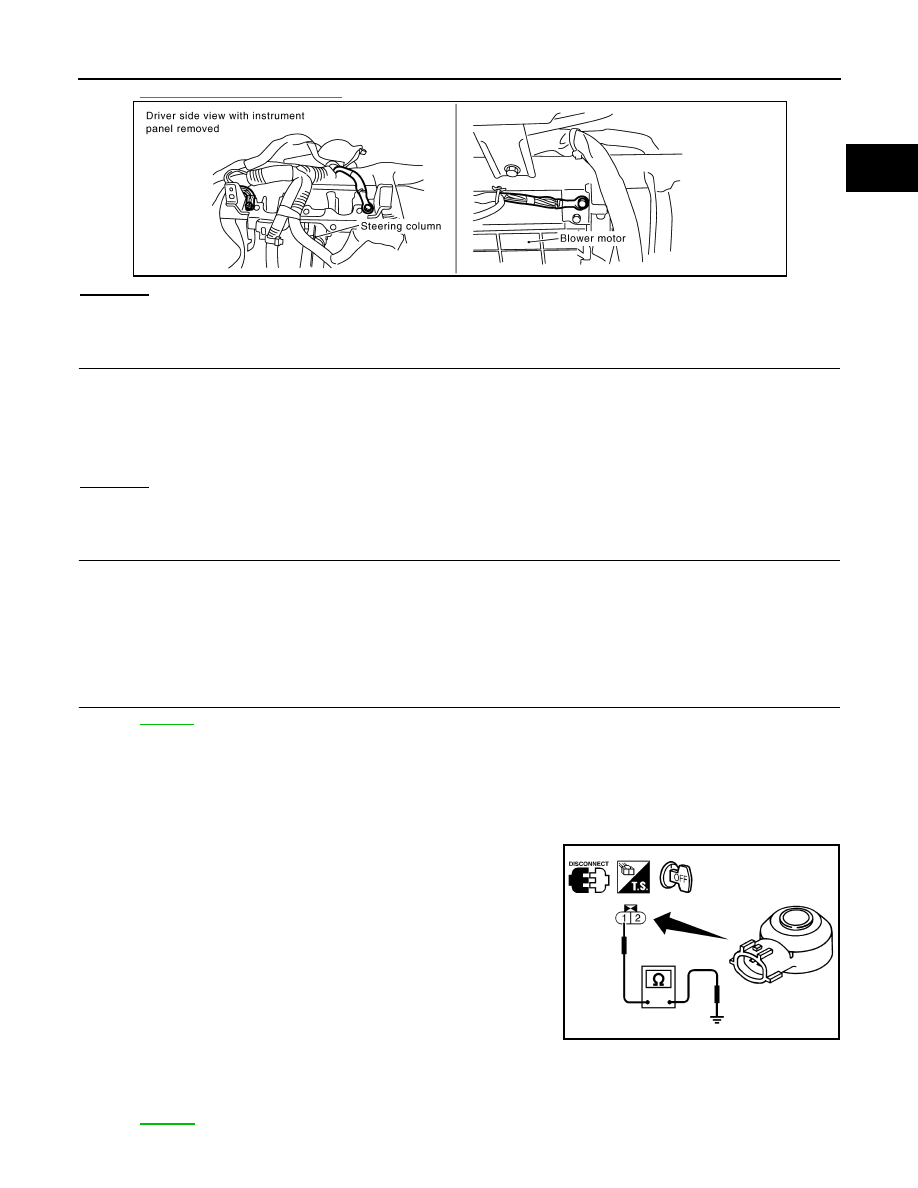
Component Inspection

INFOID:0000000001326736

KNOCK SENSOR

Check resistance between knock sensor terminal 1 and ground.
NOTE:
It is necessary to use an ohmmeter which can measure more
than 10 M

.

CAUTION:

Do not use any knock sensors that have been dropped or phys-
ically damaged. Use only new ones.

Removal and Installation

INFOID:0000000001326737

KNOCK SENSOR

Refer to 

EM-241

.

PBIB2195E

Continuity should exist.

Resistance: Approximately 532 - 588 k

 [at 20

°

C (68

°

F)]

SEF111Y

EC-906

< SERVICE INFORMATION >

[VK45DE]

DTC P0335 CKP SENSOR (POS)

DTC P0335 CKP SENSOR (POS)

Component Description

INFOID:0000000001326738

The crankshaft position sensor (POS) is located on the A/T assem-
bly facing the gear teeth (cogs) of the signal plate. It detects the fluc-
tuation of the engine revolution.
The sensor consists of a permanent magnet and Hall IC.
When the engine is running, the high and low parts of the teeth
cause the gap with the sensor to change.
The changing gap causes the magnetic field near the sensor to
change.
Due to the changing magnetic field, the voltage from the sensor
changes.
The ECM receives the voltage signal and detects the fluctuation of
the engine revolution.
ECM receives the signals as shown in the figure.

CONSULT-III Reference Value in Data Monitor Mode

INFOID:0000000001326739

Specification data are reference values.

On Board Diagnosis Logic

INFOID:0000000001326740

DTC Confirmation Procedure

INFOID:0000000001326741

NOTE:
If DTC Confirmation Procedure has been previously conducted, always turn ignition switch OFF and wait at
least 10 seconds before conducting the next test.
TESTING CONDITION:
Before performing the following procedure, confirm that battery voltage is more than 10.5V with igni-
tion switch ON.

1.

Crank engine for at least 2 seconds and run it for at least 5 seconds at idle speed.

2.

Check 1st trip DTC.

PBIB0562E

PBIB3459E

MONITOR ITEM

CONDITION

SPECIFICATION

ENG SPEED

• Run engine and compare CONSULT-III value with the tachometer indication.

Almost the same speed as 
the tachometer indication.

DTC No.

Trouble diagnosis name

DTC detecting condition

Possible cause

P0335
0335

Crankshaft position sen-
sor (POS) circuit

• The crankshaft position sensor (POS) signal 

is not detected by the ECM during the first 
few seconds of engine cranking.

• The proper pulse signal from the crankshaft 

position sensor (POS) is not sent to ECM 
while the engine is running.

• The crankshaft position sensor (POS) signal 

is not in the normal pattern during engine run-
ning.

• Harness or connectors

(The sensor circuit is open or shorted)

• Crankshaft position sensor (POS)
• Signal plate

DTC P0335 CKP SENSOR (POS)

EC-907

< SERVICE INFORMATION >

[VK45DE]

C

D

E

F

G

H

I

J

K

L

M

A

EC

N

P

O

3.

If 1st trip DTC is detected, go to 

EC-908, "Diagnosis Procedure"

.

Wiring Diagram

INFOID:0000000001326742

Specification data are reference values and are measured between each terminal and ground.
Pulse signal is measured by CONSULT-III.

CAUTION:

TBWM1336E

EC-908

< SERVICE INFORMATION >

[VK45DE]

DTC P0335 CKP SENSOR (POS)

Do not use ECM ground terminals when measuring input/output voltage. Doing so may result in dam-
age to the ECM's transistor. Use a ground other than ECM terminals, such as the ground.

: Average voltage for pulse signal (Actual pulse signal can be confirmed by oscilloscope.)

Diagnosis Procedure

INFOID:0000000001326743

1.

CHECK GROUND CONNECTIONS

1.

Turn ignition switch OFF.

2.

Loosen and retighten three ground screws on the body.
Refer to 

EC-723, "Ground Inspection"

.

OK or NG

OK

>> GO TO 2.

NG

>> Repair or replace ground connections.

2.

CHECK CRANKSHAFT POSITION (CKP) SENSOR (POS) POWER SUPPLY CIRCUIT

TER-

MI-

NAL 

NO.

WIRE 

COLOR

ITEM

CONDITION

DATA (DC Voltage)

13

Y

Crankshaft position sensor 
(POS)

[Engine is running]
• Warm-up condition
• Idle speed

NOTE:
The pulse cycle changes depending on rpm 
at idle

1.0 - 2.0V

[Engine is running]
• Engine speed: 2,000 rpm

1.0 - 2.0V

111

W/B

ECM relay
(Self shut-off)

[Engine is running]
[Ignition switch: OFF]
• For a few seconds after turning ignition 

switch OFF

0 - 1.5V

[Ignition switch: OFF]
• More than a few seconds after turning igni-

tion switch OFF

BATTERY VOLTAGE
(11 - 14V)

119

120

R
R/B

Power supply for ECM

[Ignition switch: ON]

BATTERY VOLTAGE
(11 - 14V)

PBIB1041E

PBIB1042E

PBIB2195E


Content   ..  534  535  536  537   ..