Infiniti FX35 / FX45. Manual - part 528
DTC P0172, P0175 FUEL INJECTION SYSTEM FUNCTION
EC-873
< SERVICE INFORMATION >
[VK45DE]
C
D
E
F
G
H
I
J
K
L
M
A
EC
N
P
O
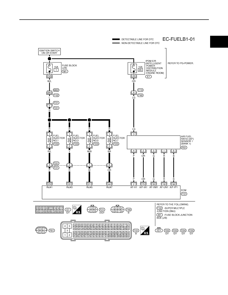
Wiring Diagram
INFOID:0000000001326704
BANK 1
Specification data are reference values and are measured between each terminal and ground.
Pulse signal is measured by CONSULT-III.
CAUTION:
TBWM1332E