Infiniti FX35 / FX45. Manual - part 519


  Index      Infiniti     Infiniti FX35 / FX45 (S50) - service repair manual 2008 year


Search            


Content   ..  517  518  519  520   ..


Infiniti FX35 / FX45. Manual - part 519


DTC P0137, P0157 HO2S2

EC-837

< SERVICE INFORMATION >

[VK45DE]

C

D

E

F

G

H

I

J

K

L

M

A

EC

N

P

O

3.

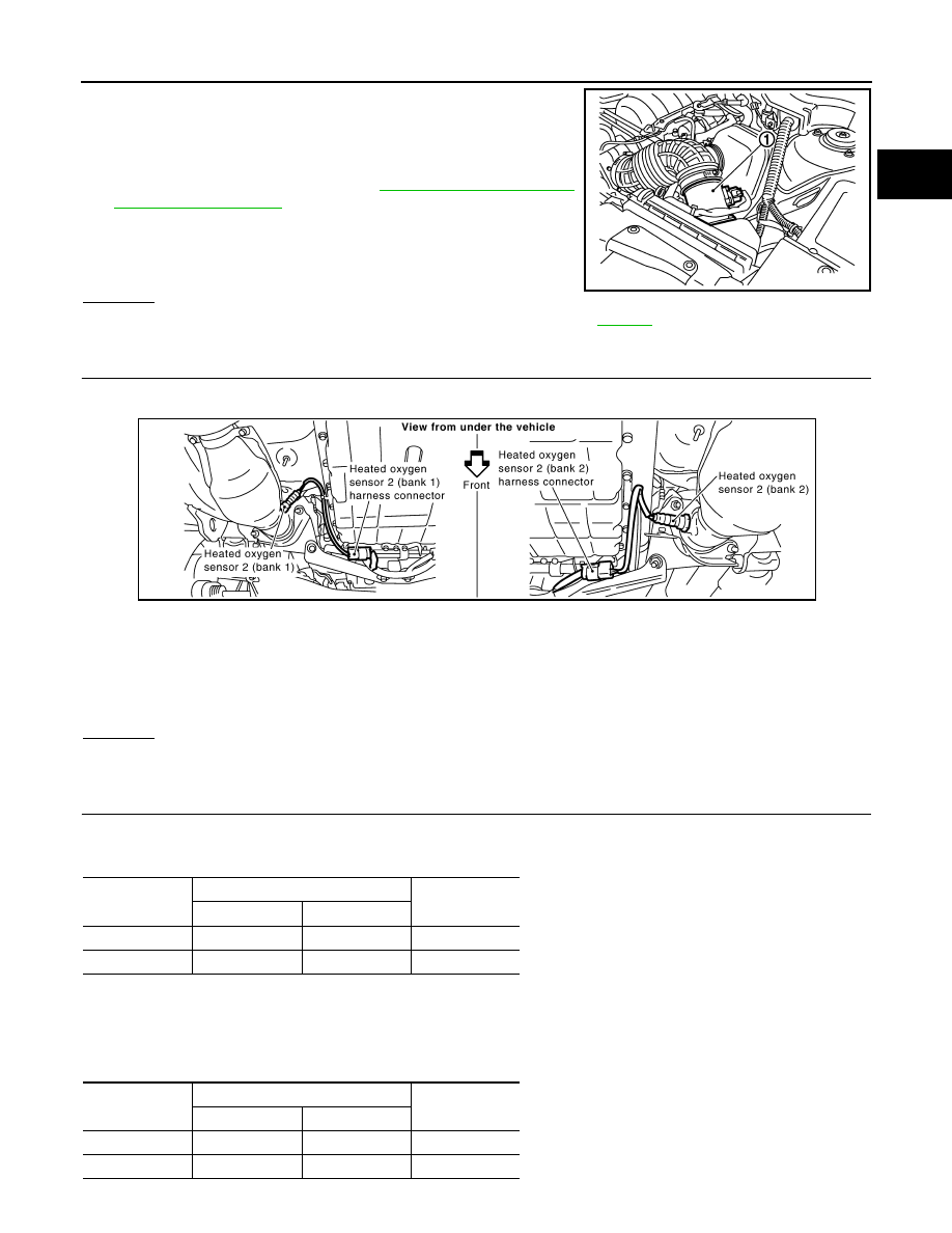
Disconnect mass air flow sensor (1) harness connector, and
restart and run engine for at least 5 seconds at idle speed.

4.

Stop engine and reconnect mass air flow sensor harness con-
nector.

5.

Make sure DTC P0102 is displayed.

6.

Erase the DTC memory. Refer to 

EC-633, "Emission-related

Diagnostic Information"

.

7.

Make sure DTC P0000 is displayed.

8.

Run engine for at least 10 minutes at idle speed.
Is the 1st trip DTC P0171 or P0174 detected?
Is it difficult to start engine?

Yes or No

Yes

>> Perform trouble diagnosis for DTC P0171, P0174. Refer to 

EC-861

.

No

>> GO TO 3.

3.

CHECK HO2S2 GROUND CIRCUIT FOR OPEN AND SHORT

1.

Turn ignition switch OFF.

2.

Disconnect heated oxygen sensor 2 harness connector.

3.

Disconnect ECM harness connector.

4.

Check harness continuity between HO2S2 terminal 4 and ECM terminal 78.
Refer to Wiring Diagram.

5.

Also check harness for short to ground and short to power.

OK or NG

OK

>> GO TO 4.

NG

>> Repair open circuit or short to ground or short to power in harness or connectors.

4.

CHECK HO2S2 INPUT SIGNAL CIRCUIT FOR OPEN AND SHORT

1.

Check harness continuity between ECM terminal and HO2S2 terminal as follows.
Refer to Wiring Diagram.

2.

Check harness continuity between the following terminals and ground.
Refer to Wiring Diagram.

PBIB3230E

Continuity should exist.

PBIB1534E

DTC

Terminals

Bank

ECM

Sensor

P0137

55

1

1

P0157

74

1

2

Continuity should exist.

DTC

Terminals

Bank

ECM

Sensor

P0137

55

1

1

P0157

74

1

2

EC-838

< SERVICE INFORMATION >

[VK45DE]

DTC P0137, P0157 HO2S2

3.

Also check harness for short to power.

OK or NG

OK

>> GO TO 5.

NG

>> Repair open circuit or short to ground or short to power in harness or connectors.

5.

CHECK HEATED OXYGEN SENSOR 2

Refer to 

EC-838, "Component Inspection"

.

OK or NG

OK

>> GO TO 6.

NG

>> Replace malfunctioning heated oxygen sensor 2.

6.

CHECK INTERMITTENT INCIDENT

Refer to 

EC-717

.

>> INSPECTION END

Component Inspection

INFOID:0000000001326678

HEATED OXYGEN SENSOR 2

 With CONSULT-III

1.

Start engine and warm it up to the normal operating temperature.

2.

Turn ignition switch OFF and wait at least 10 seconds.

3.

Start engine and keep the engine speed between 3,500 and 4,000 rpm for at least 1 minute under no load.

4.

Let engine idle for 1 minute.

5.

Select “FUEL INJECTION” in “ACTIVE TEST” mode with CONSULT-III, and select “HO2S2 (B1)/(B2)” as
the monitor item.

6.

Check “HO2S2 (B1)/(B2)” at idle speed when adjusting “FUEL INJECTION” to 

±

25%.

“HO2S2 (B1)/(B2)” should be above 0.78V at least once when the “FUEL INJECTION” is +25%.
“HO2S2 (B1)/(B2)” should be below 0.18V at least once when the “FUEL INJECTION” is 

25%.

CAUTION:

• Discard any heated oxygen sensor which has been dropped from a height of more than 0.5 m (19.7

in) onto a hard surface such as a concrete floor; use a new one.

• Before installing new oxygen sensor, clean exhaust system threads using Oxygen Sensor Thread

Cleaner tool J-43897-18 or J-43897-12 and approved anti-seize lubricant.

 Without CONSULT-III

1.

Start engine and warm it up to the normal operating temperature.

2.

Turn ignition switch OFF and wait at least 10 seconds.

3.

Start engine and keep the engine speed between 3,500 and 4,000 rpm for at least 1 minute under no load.

4.

Let engine idle for 1 minute.

5.

Set voltmeter probes between ECM terminal 55 [HO2S2 (B1) signal] or 74 [HO2S2 (B2) signal] and
ground.

Continuity should not exist.

JMBIA0640GB

DTC P0137, P0157 HO2S2

EC-839

< SERVICE INFORMATION >

[VK45DE]

C

D

E

F

G

H

I

J

K

L

M

A

EC

N

P

O

6.

Check the voltage when revving up to 4,000 rpm under no load
at least 10 times.
(Depress and release accelerator pedal as soon as possible.)
The voltage should be above 0.78V at least once during this
procedure.
If the voltage is above 0.78V at step 6, step 7 is not neces-
sary.

7.

Keep vehicle at idling for 10 minutes, then check voltage. Or
check the voltage when coasting from 80 km/h (50 MPH) in D
position.
The voltage should be below 0.18V at least once during this
procedure.

8.

If NG, replace heated oxygen sensor 2.

CAUTION:

• Discard any heated oxygen sensor which has been dropped from a height of more than 0.5 m (19.7

in) onto a hard surface such as a concrete floor; use a new one.

• Before installing new oxygen sensor, clean exhaust system threads using Oxygen Sensor Thread

Cleaner tool J-43897-18 or J-43897-12 and approved anti-seize lubricant.

Removal and Installation

INFOID:0000000001326679

HEATED OXYGEN SENSOR 2

Refer to 

EM-179

PBIB2024E

EC-840

< SERVICE INFORMATION >

[VK45DE]

DTC P0138, P0158 HO2S2

DTC P0138, P0158 HO2S2

Component Description

INFOID:0000000001326680

The heated oxygen sensor 2, after three way catalyst (manifold),
monitors the oxygen level in the exhaust gas on each bank.
Even if switching characteristics of the air fuel ratio (A/F) sensor 1
are shifted, the air-fuel ratio is controlled to stoichiometric, by the sig-
nal from the heated oxygen sensor 2.
This sensor is made of ceramic zirconia. The zirconia generates volt-
age from approximately 1V in richer conditions to 0V in leaner condi-
tions.
Under normal conditions the heated oxygen sensor 2 is not used for
engine control operation.

CONSULT-III Reference Value in Data Monitor Mode

INFOID:0000000001326681

Specification data are reference values.

On Board Diagnosis Logic

INFOID:0000000001326682

The heated oxygen sensor 2 has a much longer switching time between rich and lean than the A/F sensor 1.
The oxygen storage capacity of the three way catalyst (manifold) causes the longer switching time.
MALFUNCTION A
To judge the malfunctions of heated oxygen sensor 2, ECM monitors
whether the voltage is unusually high during the various driving con-
dition such as fuel-cut.

MALFUNCTION B

SEF327R

MONITOR ITEM

CONDITION

SPECIFICATION

HO2S2 (B1)
HO2S2 (B2)

• Revving engine from idle to 3,000 rpm quickly after the following conditions 

are met.

- Engine: After warming up
- Keeping the engine speed between 3,500 and 4,000 rpm for 1 minute and at 

idle for 1 minute under no load

0 - 0.3V 

←→

 Approx. 0.6 - 

1.0V

HO2S2 MNTR (B1)
HO2S2 MNTR (B2)

• Revving engine from idle to 3,000 rpm quickly after the following conditions 

are met.

- Engine: After warming up
- Keeping the engine speed between 3,500 and 4,000 rpm for 1 minute and at 

idle for 1 minute under no load

LEAN 

←→

 RICH

PBIB1848E


Content   ..  517  518  519  520   ..