Infiniti FX35 / FX45. Manual - part 501


  Index      Infiniti     Infiniti FX35 / FX45 (S50) - service repair manual 2008 year


Search            


Content   ..  499  500  501  502   ..


Infiniti FX35 / FX45. Manual - part 501


DTC P0101 MAF SENSOR

EC-765

< SERVICE INFORMATION >

[VK45DE]

C

D

E

F

G

H

I

J

K

L

M

A

EC

N

P

O

4.

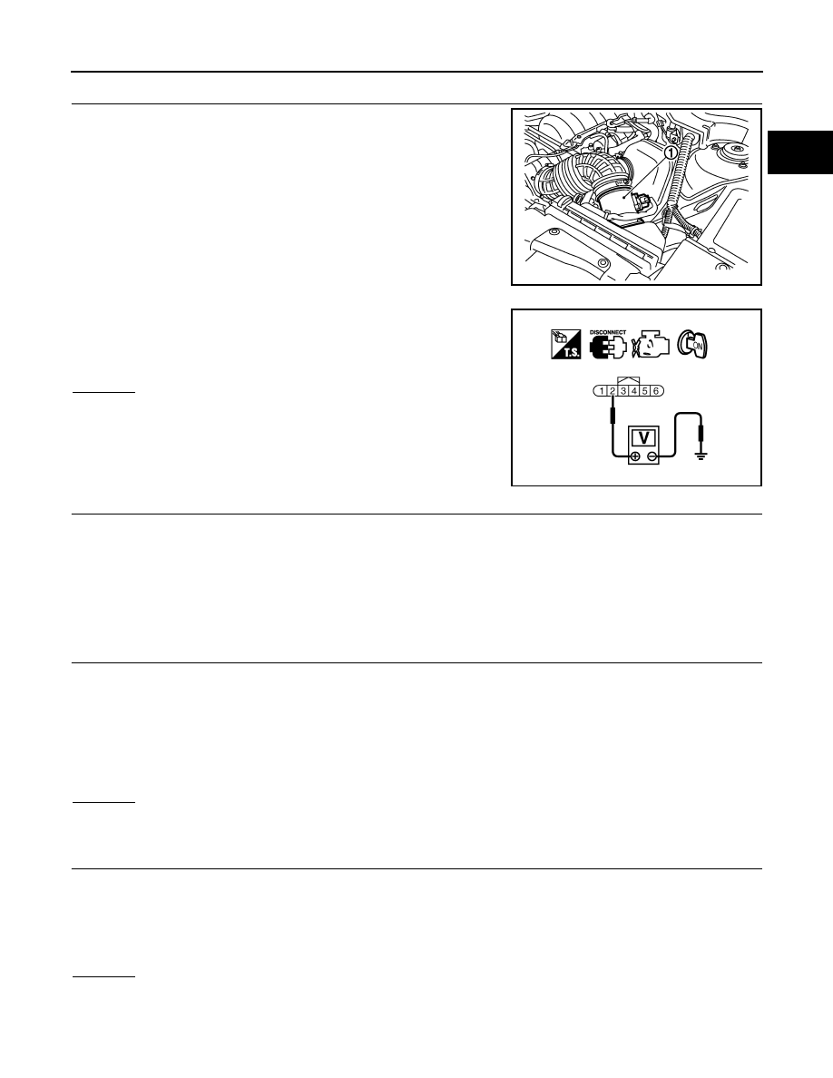
CHECK MAF SENSOR POWER SUPPLY CIRCUIT

1.

Disconnect mass air flow (MAF) sensor (1) harness connector.

2.

Turn ignition switch ON.

3.

Check voltage between MAF sensor terminal 2 and ground with
CONSULT-III or tester.

OK or NG

OK

>> GO TO 6.

NG

>> GO TO 5.

5.

DETECT MALFUNCTIONING PART

Check the following.
• Harness connectors E211, M41
• Harness connectors M82, F102
• Harness for open or short between mass air flow sensor and ECM
• Harness for open or short between mass air flow sensor and IPDM E/R

>> Repair open circuit or short to ground or short to power in harness or connectors.

6.

CHECK MAF SENSOR GROUND CIRCUIT FOR OPEN AND SHORT

1.

Turn ignition switch OFF.

2.

Disconnect ECM harness connector.

3.

Check harness continuity between MAF sensor terminal 3 and ECM terminal 67.
Refer to Wiring Diagram.

4.

Also check harness for short to ground and short to power.

OK or NG

OK

>> GO TO 7.

NG

>> Repair open circuit or short to ground or short to power in harness or connectors.

7.

CHECK MAF SENSOR INPUT SIGNAL CIRCUIT FOR OPEN AND SHORT

1.

Check harness continuity between MAF sensor terminal 4 and ECM terminal 51.
Refer to Wiring Diagram.

2.

Also check harness for short to ground and short to power.

OK or NG

OK

>> GO TO 8.

NG

>> Repair open circuit or short to ground or short to power in harness or connectors.

PBIB3230E

Voltage: Battery voltage

PBIB1168E

Continuity should exist.

Continuity should exist.

EC-766

< SERVICE INFORMATION >

[VK45DE]

DTC P0101 MAF SENSOR

8.

CHECK INTAKE AIR TEMPERATURE SENSOR

Refer to 

EC-778, "Component Inspection"

.

OK or NG

OK

>> GO TO 9.

NG

>> Replace intake air temperature sensor.

9.

CHECK EVAP CONTROL SYSTEM PRESSURE SENSOR

Refer to 

EC-958, "Component Inspection"

.

OK or NG

OK

>> GO TO 10.

NG

>> Replace EVAP control system pressure sensor.

10.

CHECK MASS AIR FLOW SENSOR

Refer to 

EC-766, "Component Inspection"

.

OK or NG

OK

>> GO TO 11.

NG

>> Replace mass air flow sensor.

11.

CHECK INTERMITTENT INCIDENT

Refer to 

EC-717

.

>> INSPECTION END

Component Inspection

INFOID:0000000001326593

MASS AIR FLOW SENSOR

 With CONSULT-III

1.

Reconnect all harness connectors disconnected.

2.

Start engine and warm it up to normal operating temperature.

3.

Connect CONSULT-III and select “DATA MONITOR” mode.

4.

Select “MAS A/F SE-B1” and check indication under the following conditions.

*: Check for linear voltage rise in response to engine being increased to about 4,000 rpm.

5.

If the voltage is out of specification, proceed the following.

a.

Check for the cause of uneven air flow through mass air flow sensor. Refer to following.
• Crushed air ducts
• Malfunctioning seal of air cleaner element
• Uneven dirt of air cleaner element
• Improper specification of intake air system parts

b.

If NG, repair or replace malfunctioning part and perform step 2 to 4 again.
If OK, go to next step.

6.

Turn ignition switch OFF.

7.

Disconnect mass air flow sensor harness connector and reconnect it again.

8.

Perform step 2 to 4 again.

9.

If NG, clean or replace mass air flow sensor.

Condition

MAS A/F SE-B1 (V)

Ignition switch ON (Engine stopped.)

Approx. 0.4

Idle (Engine is warmed-up to normal 
operating temperature.)

1.0 - 1.3

2,500 rpm (Engine is warmed-up to 
normal operating temperature.)

1.6 - 2.0

Idle to about 4,000 rpm

1.0 - 1.3 to Approx. 2.4*

DTC P0101 MAF SENSOR

EC-767

< SERVICE INFORMATION >

[VK45DE]

C

D

E

F

G

H

I

J

K

L

M

A

EC

N

P

O

 Without CONSULT-III

1.

Reconnect all harness connectors disconnected.

2.

Start engine and warm it up to normal operating temperature.

3.

Check voltage between ECM terminal 51 (Mass air flow sensor
signal) and ground.

*: Check for linear voltage rise in response to engine being increased to about 4,000 rpm.

4.

If the voltage is out of specification, proceed the following.

a.

Check for the cause of uneven air flow through mass air flow sensor. Refer to following.
• Crushed air ducts
• Malfunctioning seal of air cleaner element
• Uneven dirt of air cleaner element
• Improper specification of intake air system parts

b.

If NG, repair or replace malfunctioning part and perform step 2 and 3 again.
If OK, go to next step.

5.

Turn ignition switch OFF.

6.

Disconnect mass air flow sensor harness connector and reconnect it again.

7.

Perform step 2 and 3 again.

8.

If NG, clean or replace mass air flow sensor.

Removal and Installation

INFOID:0000000001326594

MASS AIR FLOW SENSOR

Refer to 

EM-173

.

Condition

Voltage V

Ignition switch ON (Engine stopped.)

Approx. 0.4

Idle (Engine is warmed-up to normal 
operating temperature.)

1.0 - 1.3

2,500 rpm (Engine is warmed-up to 
normal operating temperature.)

1.6 - 2.0

Idle to about 4,000 rpm

1.0 - 1.3 to Approx. 2.4*

PBIB1106E

EC-768

< SERVICE INFORMATION >

[VK45DE]

DTC P0102, P0103 MAF SENSOR

DTC P0102, P0103 MAF SENSOR

Component Description

INFOID:0000000001326595

The mass air flow sensor is placed in the stream of intake air. It mea-
sures the intake flow rate by measuring a part of the entire intake
flow. The mass air flow sensor controls the temperature of the hot
wire to a certain amount. The heat generated by the hot wire is
reduced as the intake air flows around it. The more air, the greater
the heat loss. 
Therefore, the electric current supplied to hot wire is changed to
maintain the temperature of the hot wire as air flow increases. The
ECM detects the air flow by means of this current change.

CONSULT-III Reference Value in Data Monitor Mode

INFOID:0000000001326596

Specification data are reference values.

On Board Diagnosis Logic

INFOID:0000000001326597

These self-diagnoses have the one trip detection logic.

FAIL-SAFE MODE

When the malfunction is detected, the ECM enters fail-safe mode and the MIL lights up.

DTC Confirmation Procedure

INFOID:0000000001326598

NOTE:
If DTC Confirmation Procedure has been previously conducted, always turn ignition switch OFF and wait at
least 10 seconds before conducting the next test.

PROCEDURE FOR DTC P0102

1.

Start engine and wait at least 5 seconds.

2.

Check DTC.

PBIB1604E

MONITOR ITEM

CONDITION

SPECIFICATION

MAS A/F SE-B1

See 

EC-709

.

CAL/LD VALUE

• Engine: After warming up
• Selector lever: P or N
• Air conditioner switch: OFF
• No  load

Idle

14% - 33%

2,500 rpm

12% - 25%

MASS AIRFLOW

• Engine: After warming up
• Selector lever: P or N
• Air conditioner switch: OFF
• No  load

Idle

2.0 - 6.0 g·m/s

2,500 rpm

7.0 - 20.0 g·m/s

DTC No.

Trouble diagnosis 

name

DTC detecting condition

Possible cause

P0102
0102

Mass air flow sensor 
circuit low input

An excessively low voltage from the sensor is sent 
to ECM.

• Harness or connectors

(The sensor circuit is open or shorted.)

• Intake air leaks
• Mass air flow sensor

P0103
0103

Mass air flow sensor 
circuit high input

An excessively high voltage from the sensor is 
sent to ECM.

• Harness or connectors

(The sensor circuit is open or shorted.)

• Mass air flow sensor

Detected items

Engine operating condition in fail-safe mode

Mass air flow sensor circuit

Engine speed will not rise more than 2,400 rpm due to the fuel cut.


Content   ..  499  500  501  502   ..