Infiniti FX35 / FX45. Manual - part 491
DTC U1000, U1001 CAN COMMUNICATION LINE
EC-725
< SERVICE INFORMATION >
[VK45DE]
C
D
E
F
G
H
I
J
K
L
M
A
EC
N
P
O
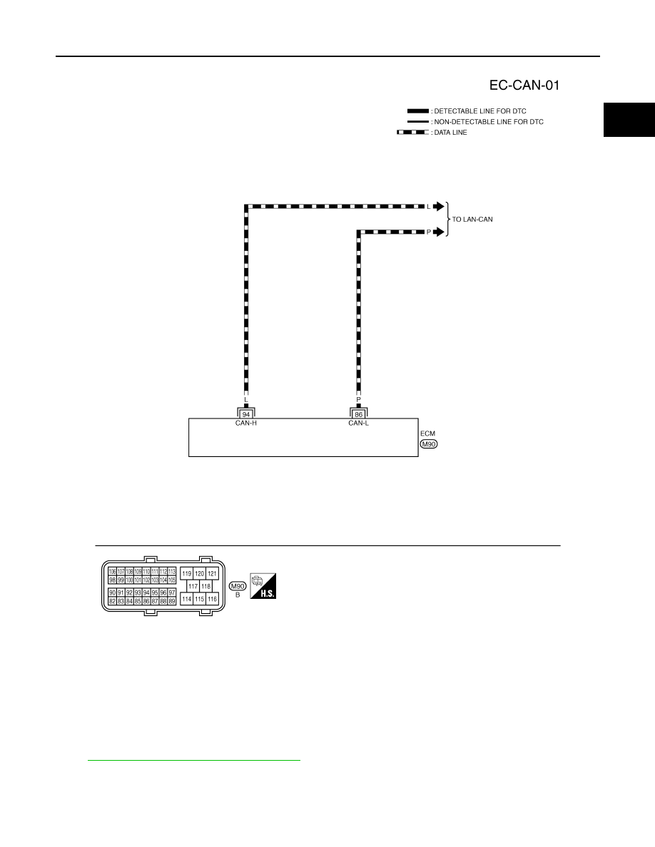
Wiring Diagram
INFOID:0000000001326548
Diagnosis Procedure
INFOID:0000000001326549
LAN-43, "CAN System Specification Chart"
.
TBWM1322E