Infiniti FX35 / FX45. Manual - part 437


  Index      Infiniti     Infiniti FX35 / FX45 (S50) - service repair manual 2008 year


Search            


Content   ..  435  436  437  438   ..


Infiniti FX35 / FX45. Manual - part 437


DTC P2122, P2123 APP SENSOR

EC-509

< SERVICE INFORMATION >

[VQ35DE]

C

D

E

F

G

H

I

J

K

L

M

A

EC

N

P

O

Diagnosis Procedure

INFOID:0000000001326392
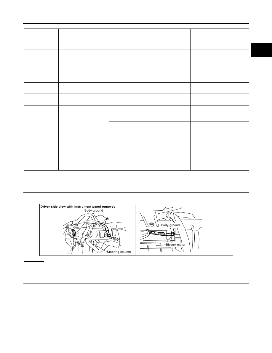
1.

CHECK GROUND CONNECTIONS

1.

Turn ignition switch OFF.

2.

Loosen and retighten ground screw on the body. Refer to 

EC-144, "Ground Inspection"

.

OK or NG

OK

>> GO TO 2.

NG

>> Repair or replace ground connections.

2.

CHECK ACCELERATOR PEDAL POSITION SENSOR 1 POWER SUPPLY CIRCUIT

TER-

MI-

NAL 

NO.

WIRE 

COLOR

ITEM

CONDITION

DATA (DC Voltage)

82

B/W

Sensor ground
(APP sensor 1)

[Engine is running]
• Warm-up condition
• Idle speed

Approximately 0V

83

G/OR

Sensor ground
(APP sensor 2)

[Engine is running]
• Warm-up condition
• Idle speed

Approximately 0V

90

L/B

Sensor power supply
(APP sensor 1)

[Ignition switch: ON]

Approximately 5V

91

G

Sensor power supply
(APP sensor 2)

[Ignition switch: ON]

Approximately 5V

98

Y/R

Accelerator pedal position 
sensor 2

[Ignition switch: ON]
• Engine stopped
• Accelerator pedal: Fully released

0.15 - 0.60V

[Ignition switch: ON]
• Engine stopped
• Accelerator pedal: Fully depressed

1.95 - 2.40V

106

OR

Accelerator pedal position 
sensor 1

[Ignition switch: ON]
• Engine stopped
• Accelerator pedal: Fully released

0.5 - 1.0V

[Ignition switch: ON]
• Engine stopped
• Accelerator pedal: Fully depressed

3.9 - 4.7V

PBIB2625E

EC-510

< SERVICE INFORMATION >

[VQ35DE]

DTC P2122, P2123 APP SENSOR

1.

Disconnect accelerator pedal position (APP) sensor harness
connector.

2.

Turn ignition switch ON.

3.

Check voltage between APP sensor terminal 6 and ground with
CONSULT-III or tester.

OK or NG

OK

>> GO TO 4.

NG

>> GO TO 3.

3.

DETECT MALFUNCTIONING PART

Check the following.
• Harness connectors E211, M41
• Harness for open or short between ECM and APP sensor

>> Repair open circuit or short to ground or short to power in harness or connectors.

4.

CHECK ACCELERATOR PEDAL POSITION SENSOR 1 GROUND CIRCUIT FOR OPEN AND SHORT

1.

Turn ignition switch OFF.

2.

Disconnect ECM harness connector.

3.

Check harness continuity between APP sensor terminal 3 and ECM terminal 82.
Refer to Wiring Diagram.

4.

Also check harness for short to ground and short to power.

OK or NG

OK

>> GO TO 6.

NG

>> GO TO 5.

5.

DETECT MALFUNCTIONING PART

Check the following.
• Harness connectors E211, M41
• Harness for open or short between ECM and APP sensor

>> Repair open circuit or short to ground or short to power in harness or connectors.

6.

CHECK ACCELERATOR PEDAL POSITON SENSOR INPUT SIGNAL CIRCUIT FOR OPEN AND SHORT

1.

Check harness continuity between ECM terminal 106 and APP sensor terminal 5.
Refer to Wiring Diagram.

2.

Also check harness for short to ground and short to power.

OK or NG

PBIB1580E

Voltage: Approximately 5V

PBIB0914E

Continuity should exist.

Continuity should exist.

DTC P2122, P2123 APP SENSOR

EC-511

< SERVICE INFORMATION >

[VQ35DE]

C

D

E

F

G

H

I

J

K

L

M

A

EC

N

P

O

OK

>> GO TO 8.

NG

>> GO TO 7.

7.

DETECT MALFUNCTIONING PART

Check the following.
• Harness connectors E211, M41
• Harness for open or short between ECM and APP sensor

>> Repair open circuit or short to ground or short to power in harness or connectors.

8.

CHECK ACCELERATOR PEDAL POSITION SENSOR

Refer to 

EC-511, "Component Inspection"

.

OK or NG

OK

>> GO TO 10.

NG

>> GO TO 9.

9.

REPLACE ACCELERATOR PEDAL ASSEMBLY

1.

Replace accelerator pedal assembly.

2.

Perform 

EC-85, "Accelerator Pedal Released Position Learning"

.

3.

Perform 

EC-85, "Throttle Valve Closed Position Learning"

.

4.

Perform 

EC-85, "Idle Air Volume Learning"

.

>> INSPECTION END

10.

CHECK INTERMITTENT INCIDENT

Refer to 

EC-139

.

>> INSPECTION END

Component Inspection

INFOID:0000000001326393

ACCELERATOR PEDAL POSITION SENSOR

1.

Reconnect all harness connectors disconnected.

2.

Turn ignition switch ON.

3.

Check voltage between ECM terminals 106 (APP sensor 1 sig-
nal), 98 (APP sensor 2 signal) and ground under the following
conditions.

4.

If NG, replace accelerator pedal assembly and go to next step.

5.

Perform 

EC-85, "Accelerator Pedal Released Position Learning"

.

6.

Perform 

EC-85, "Throttle Valve Closed Position Learning"

.

7.

Perform 

EC-85, "Idle Air Volume Learning"

.

Removal and Installation

INFOID:0000000001326394

ACCELERATOR PEDAL

Refer to 

ACC-3

.

Terminal

Accelerator pedal

Voltage

106
 (Accelerator pedal position 
sensor 1)

Fully released

0.5 - 1.0V

Fully depressed

3.9 - 4.7V

98
(Accelerator pedal position 
sensor 2)

Fully released

0.15 - 0.60V

Fully depressed

1.95 - 2.40V

MBIB0023E

EC-512

< SERVICE INFORMATION >

[VQ35DE]

DTC P2127, P2128 APP SENSOR

DTC P2127, P2128 APP SENSOR

Component Description

INFOID:0000000001326395

The accelerator pedal position (APP) sensor is installed on the upper
end of the accelerator pedal assembly. The sensor detects the
accelerator position and sends a signal to the ECM.
Accelerator pedal position sensor has two sensors. These sensors
are a kind of potentiometers which transform the accelerator pedal
position into output voltage, and emit the voltage signal to the ECM.
In addition, these sensors detect the opening and closing speed of
the accelerator pedal and feed the voltage signals to the ECM. The
ECM judges the current opening angle of the accelerator pedal from
these signals and controls the throttle control motor based on these
signals.
Idle position of the accelerator pedal is determined by the ECM
receiving the signal from the accelerator pedal position sensor. The ECM uses this signal for the engine oper-
ation such as fuel cut.

CONSULT-III Reference Value in Data Monitor Mode

INFOID:0000000001326396

Specification data are reference values.

*: Accelerator pedal position sensor 2 signal is converted by ECM internally. Thus, it differs from ECM terminal voltage.

On Board Diagnosis Logic

INFOID:0000000001326397

These self-diagnoses have the one trip detection logic.

FAIL-SAFE MODE

When the malfunction is detected, ECM enters fail-safe mode and the MIL lights up.

DTC Confirmation Procedure

INFOID:0000000001326398

NOTE:
If DTC Confirmation Procedure has been previously conducted, always turn ignition switch OFF and wait at
least 10 seconds before conducting the next test.

PBIB1741E

MONITOR ITEM

CONDITION

SPECIFICATION

ACCEL SEN 1

• Ignition switch: ON

(Engine stopped)

Accelerator pedal: Fully released

0.5 - 1.0V

Accelerator pedal: Fully depressed

4.0 - 4.8V

ACCEL SEN 2*

• Ignition switch: ON

(Engine stopped)

Accelerator pedal: Fully released

0.3 - 1.2V

Accelerator pedal: Fully depressed

3.9 - 4.8V

CLSD THL POS

• Ignition switch: ON

(Engine stopped)

Accelerator pedal: Fully released

ON

Accelerator pedal: Slightly depressed

OFF

DTC No.

Trouble diagnosis name

DTC detecting condition

Possible cause

P2127
2127

Accelerator pedal posi-
tion sensor 2 circuit low 
input

An excessively low voltage from the APP sen-
sor 2 is sent to ECM.

• Harness or connectors

(APP sensor 2 circuit is open or shorted.)
(TP sensor circuit shorted.)

• Accelerator pedal position sensor

(APP sensor 2)

• Electric throttle control actuator

(TP sensor 1 and 2)

P2128
2128

Accelerator pedal posi-
tion sensor 2 circuit high 
input

An excessively high voltage from the APP sen-
sor 2 is sent to ECM.

Engine operating condition in fail-safe mode

The ECM controls the electric throttle control actuator in regulating the throttle opening in order for the idle position to be within +10 
degrees.
The ECM regulates the opening speed of the throttle valve to be slower than the normal condition.
So, the acceleration will be poor. 


Content   ..  435  436  437  438   ..