Infiniti FX35 / FX45. Manual - part 410
DTC P0460 FUEL LEVEL SENSOR
EC-401
< SERVICE INFORMATION >
[VQ35DE]
C
D
E
F
G
H
I
J
K
L
M
A
EC
N
P
O
DTC P0460 FUEL LEVEL SENSOR
Component Description
INFOID:0000000001326226
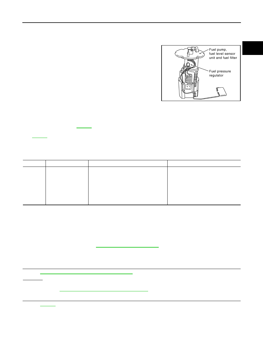
The fuel level sensor is mounted in the fuel level sensor unit. The
sensor detects a fuel level in the fuel tank and transmits a signal to
the “unified meter and A/C amp.”. The “unified meter and A/C amp.”
sends the fuel level sensor signal to the ECM through CAN commu-
nication line.
It consists of two parts, one is mechanical float and the other is vari-
able resistor. Fuel level sensor output voltage changes depending on
the movement of the fuel mechanical float.
On Board Diagnosis Logic
INFOID:0000000001326227
NOTE:
• If DTC P0460 is displayed with DTC U1000 or U1001, first perform the trouble diagnosis for DTC
U1000, U1001. Refer to
• If DTC P0460 is displayed with DTC U1010, first perform the trouble diagnosis for DTC U1010. Refer
.
When the vehicle is parked, naturally the fuel level in the fuel tank is stable. It means that output signal of the
fuel level sensor does not change. If ECM senses sloshing signal from the sensor, fuel level sensor malfunc-
tion is detected.
DTC Confirmation Procedure
INFOID:0000000001326228
NOTE:
If DTC Confirmation Procedure has been previously conducted, always turn ignition switch OFF and wait at
least 10 seconds before conducting the next test.
1.
Start engine and wait maximum of 2 consecutive minutes.
2.
Check 1st trip DTC.
3.
If 1st trip DTC is detected, go to
Diagnosis Procedure
INFOID:0000000001326229
1.
CHECK DTC WITH “UNIFIED METER AND A/C AMP.”
DI-27, "CONSULT-III Function (METER/M&A)"
OK or NG
OK
>> GO TO 2.
NG
>> Go to
DI-19, "Fuel Level Sensor Signal Inspection"
2.
CHECK INTERMITTENT INCIDENT
>> INSPECTION END
PBIB1569E
DTC No.
Trouble diagnosis name
DTC detecting condition
Possible cause
P0460
0460
Fuel level sensor circuit
noise
Even though the vehicle is parked, a signal be-
ing varied is sent from the fuel level sensor to
ECM.
• Harness or connectors
(CAN communication line is open or
shorted)
• Harness or connectors
(Fuel level sensor circuit is open or short-
ed)
• Unified meter and A/C amp.
• Fuel level sensor