Infiniti FX35 / FX45. Manual - part 402


  Index      Infiniti     Infiniti FX35 / FX45 (S50) - service repair manual 2008 year


Search            


Content   ..  400  401  402  403   ..


Infiniti FX35 / FX45. Manual - part 402


DTC P0448 EVAP CANISTER VENT CONTROL VALVE

EC-369

< SERVICE INFORMATION >

[VQ35DE]

C

D

E

F

G

H

I

J

K

L

M

A

EC

N

P

O

Diagnosis Procedure

INFOID:0000000001326197

1.

CHECK RUBBER TUBE

1.

Turn ignition switch OFF.

2.

Disconnect rubber tube connected to EVAP canister vent control valve.

3.

Check the rubber tube for clogging.

OK or NG

OK

>> GO TO 2.

NG

>> Clean rubber tube using an air blower.

2.

CHECK EVAP CANISTER VENT CONTROL VALVE

Refer to 

EC-364, "Component Inspection"

.

OK or NG

OK

>> GO TO 3.

NG

>> Replace EVAP canister vent control valve.

3.

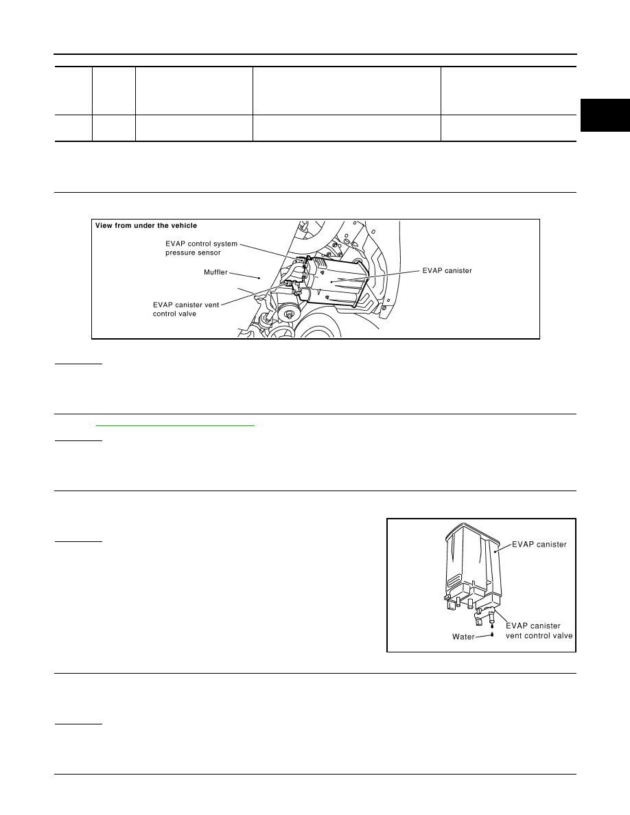
CHECK IF EVAP CANISTER SATURATED WITH WATER

1.

Remove EVAP canister with EVAP canister vent control valve and EVAP control system pressure sensor
attached.

2.

Does water drain from the EVAP canister?

Yes or No

Yes

>> GO TO 4.

No

>> GO TO 6.

4.

CHECK EVAP CANISTER

Weigh the EVAP canister with the EVAP canister vent control valve and EVAP control system pressure sensor
attached.
The weight should be less than 2.1 kg (4.6 lb).

OK or NG

OK

>> GO TO 6.

NG

>> GO TO 5.

5.

DETECT MALFUNCTIONING PART

TER-

MI-

NAL 

NO.

WIRE 

COLOR

ITEM

CONDITION

DATA (DC Voltage)

117

R/Y

EVAP canister vent control 
valve

[Ignition switch: ON]

BATTERY VOLTAGE
(11 - 14V)

PBIB1611E

PBIB1031E

EC-370

< SERVICE INFORMATION >

[VQ35DE]

DTC P0448 EVAP CANISTER VENT CONTROL VALVE

Check the following.
• EVAP canister for damage
• EVAP hose between EVAP canister and vehicle frame for clogging or poor connection

>> Repair hose or replace EVAP canister.

6.

CHECK EVAP CONTROL SYSTEM PRESSURE SENSOR CONNECTOR

1.

Disconnect EVAP control system pressure sensor harness connector.

2.

Check connectors for water.

OK or NG

OK

>> GO TO 7.

NG

>> Replace EVAP control system pressure sensor.

7.

CHECK EVAP CONTROL SYSTEM PRESSURE SENSOR

Refer to 

EC-380, "Component Inspection"

.

OK or NG

OK

>> GO TO 8.

NG

>> Replace EVAP control system pressure sensor.

8.

CHECK INTERMITTENT INCIDENT

Refer to 

EC-139

.

>> INSPECTION END

Component Inspection

INFOID:0000000001326198

EVAP CANISTER VENT CONTROL VALVE

 With CONSULT-III

1.

Remove EVAP canister vent control valve from EVAP canister.

2.

Check portion B of EVAP canister vent control valve for being
rusted.
If NG, replace EVAP canister vent control valve.
If OK, go to next step.

3.

Reconnect all harness connectors disconnected.

4.

Turn ignition switch ON.

5.

Perform “VENT CONTROL/V” in “ACTIVE TEST” mode.

6.

Check air passage continuity and operation delay time.
Make sure new O-ring is installed properly.

Operation takes less than 1 second.

If NG, replace EVAP canister vent control valve.
If OK, go to next step.

7.

Clean the air passage (Portion A to B) of EVAP canister vent control valve using an air blower.

8.

Perform step 6 again.

 Without CONSULT-III

1.

Remove EVAP canister vent control valve from EVAP canister.

Water should not exist.

Condition VENT CONTROL/V

Air passage continuity between A and B

ON

No

OFF

Yes

PBIB1033E

DTC P0448 EVAP CANISTER VENT CONTROL VALVE

EC-371

< SERVICE INFORMATION >

[VQ35DE]

C

D

E

F

G

H

I

J

K

L

M

A

EC

N

P

O

2.

Check portion B of EVAP canister vent control valve for being
rusted.

3.

Check air passage continuity and operation delay time under the
following conditions.
Make sure new O-ring is installed properly.

Operation takes less than 1 second.

If NG, replace EVAP canister vent control valve.
If OK, go to next step.

4.

Clean the air passage (Portion A to B) of EVAP canister vent control valve using an air blower.

5.

Perform step 3 again.

PBIB1033E

Condition

Air passage continuity between A and B

12V direct current supply between
 terminals 1 and 2

No

OFF

Yes

PBIB1034E

EC-372

< SERVICE INFORMATION >

[VQ35DE]

DTC P0451 EVAP CONTROL SYSTEM PRESSURE SENSOR

DTC P0451 EVAP CONTROL SYSTEM PRESSURE SENSOR

Component Description

INFOID:0000000001326199

The EVAP control system pressure sensor detects pressure in the purge line. The sensor output voltage to the
ECM increases as pressure increases.

CONSULT-III Reference Value in Data Monitor Mode

INFOID:0000000001326200

Specification data are reference values.

On Board Diagnosis Logic

INFOID:0000000001326201

NOTE:
If DTC P0451 is displayed with DTC P0643, first perform the trouble diagnosis for DTC P0643.
Refer to 

EC-424

.

DTC Confirmation Procedure

INFOID:0000000001326202

NOTE:
If DTC Confirmation Procedure has been previously conducted, always turn ignition switch OFF and wait at
least 10 seconds before conducting the next test.
1.

Start engine and wait at least 40 seconds.
NOTE:
Do not depress accelerator pedal even slightly.

2.

Check 1st trip DTC.

3.

If 1st trip DTC is detected, go to 

EC-373, "Diagnosis Procedure"

.

PBIB1611E

PBIB1207E

MONITOR ITEM

CONDITION

SPECIFICATION

EVAP SYS PRES

• Ignition switch: ON

Approx. 1.8 - 4.8V

DTC No.

Trouble diagnosis name

DTC detecting condition

Possible cause

P0451
0451

EVAP control system 
pressure sensor perfor-
mance

ECM detects a sloshing signal from the EVAP 
control system pressure sensor

• Harness or connectors
• EVAP control system pressure sensor


Content   ..  400  401  402  403   ..