Infiniti FX35 / FX45. Manual - part 379
DTC P0171, P0174 FUEL INJECTION SYSTEM FUNCTION
EC-277
< SERVICE INFORMATION >
[VQ35DE]
C
D
E
F
G
H
I
J
K
L
M
A
EC
N
P
O
Do not use ECM ground terminals when measuring input/output voltage. Doing so may result in dam-
age to the ECM's transistor. Use a ground other than ECM terminals, such as the ground.
: Average voltage for pulse signal (Actual pulse signal can be confirmed by oscilloscope.)
TER-
MI-
NAL
NO.
WIRE
COLOR
ITEM
CONDITION
DATA (DC Voltage)
2
R/L
A/F sensor 1 heater
(bank 1)
[Engine is running]
• Warm-up condition
• Idle speed
Approximately 5V
16
G
A/F sensor 1 (bank 1)
[Engine is running]
• Warm-up condition
• Idle speed
Approximately 3.1V
35
B/R
Approximately 2.6V
56
L
Approximately 2.3V
75
R/B
Approximately 2.3V
21
22
23
W
G
R
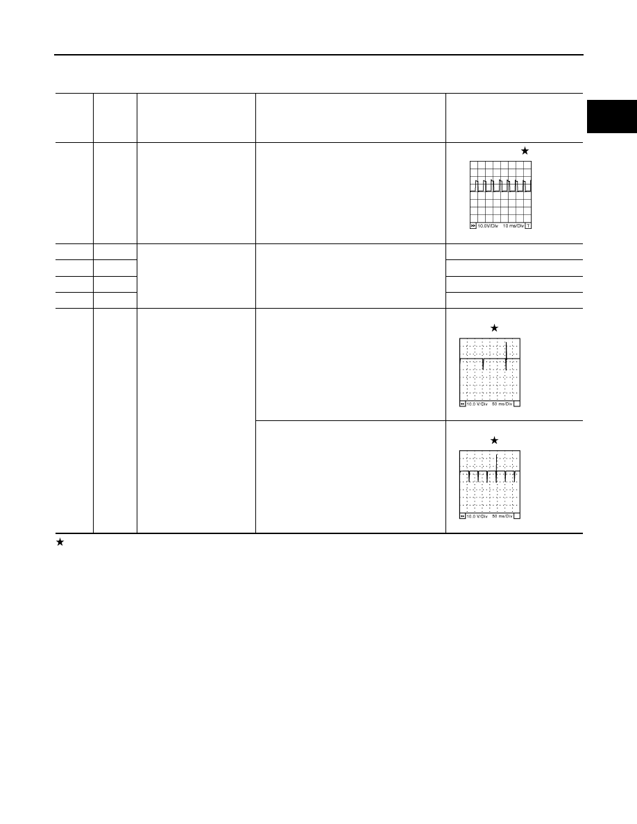
Fuel injector No. 5
Fuel injector No. 3
Fuel injector No. 1
[Engine is running]
• Warm-up condition
• Idle speed
NOTE:
The pulse cycle changes depending on rpm
at idle
BATTERY VOLTAGE
(11 - 14V)
[Engine is running]
• Warm-up condition
• Engine speed: 2,000 rpm
BATTERY VOLTAGE
(11 - 14V)
PBIB1584E
SEC984C
SEC985C