Infiniti FX35 / FX45. Manual - part 324
ON BOARD DIAGNOSTIC (OBD) SYSTEM
EC-57
< SERVICE INFORMATION >
[VQ35DE]
C
D
E
F
G
H
I
J
K
L
M
A
EC
N
P
O
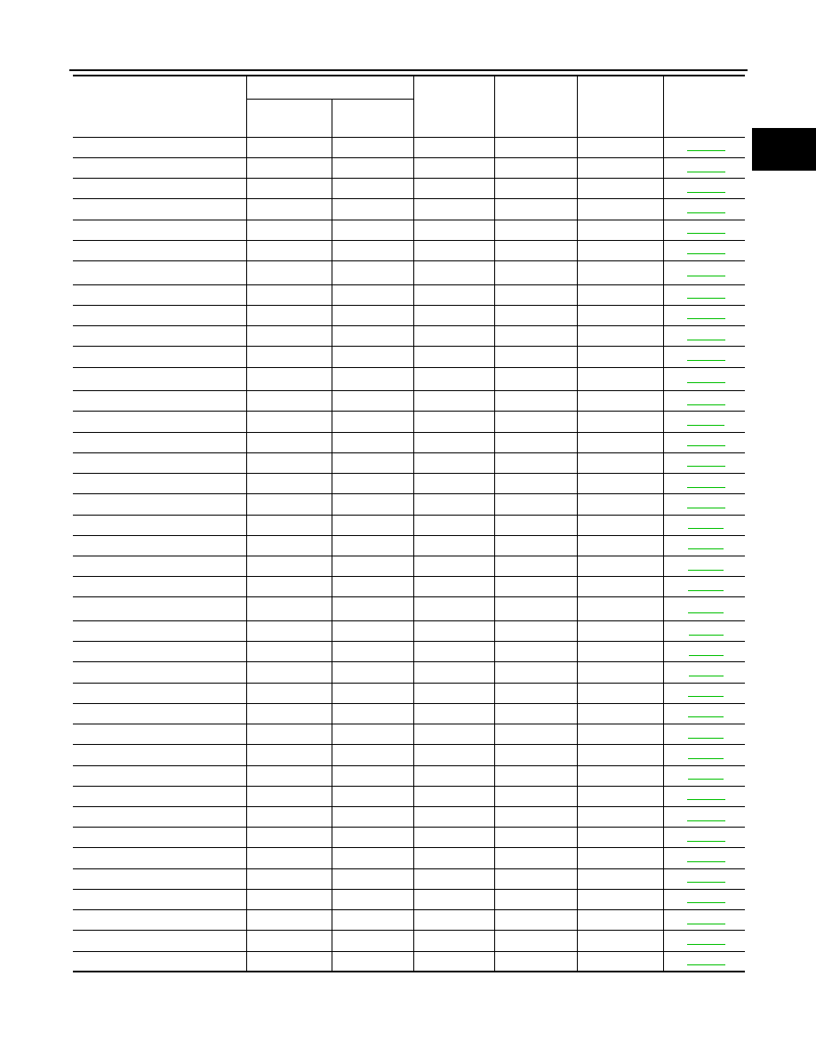
VENT CONTROL VALVE
P0447
0447
—
2
×
VENT CONTROL VALVE
P0448
0448
—
2
×
EVAP SYS PRES SEN
P0451
0451
—
2
×
EVAP SYS PRES SEN
P0452
0452
—
2
×
EVAP SYS PRES SEN
P0453
0453
—
2
×
EVAP GROSS LEAK
P0455
0455
—
2
×
EVAP VERY SML LEAK
P0456
0456
×
*
4
2
×
FUEL LEV SEN SLOSH
P0460
0460
—
2
×
FUEL LEVEL SENSOR
P0461
0461
—
2
×
FUEL LEVL SEN/CIRC
P0462
0462
—
2
×
FUEL LEVL SEN/CIRC
P0463
0463
—
2
×
VEH SPEED SEN/CIRC*
6
P0500
0500
—
2
×
ISC SYSTEM
P0506
0506
—
2
×
ISC SYSTEM
P0507
0507
—
2
×
PW ST P SEN/CIRC
P0550
0550
—
2
—
ECM BACK UP/CIRCUIT
P0603
0603
—
2
×
ECM
P0605
0605
—
1 or 2
×
or —
SENSOR POWER/CIRC
P0643
0643
—
1
×
TCM
P0700
0700
—
1
×
PNP SW/CIRC
P0705
0705
—
2
×
ATF TEMP SEN/CIRC
P0710
0710
—
2
×
TURBINE SENSOR
P0717
0717
—
2
×
VEH SPD SEN/CIR AT*
6
P0720
0720
—
2
×
A/T 1ST GR FNCTN
P0731
0731
—
2
×
A/T 2ND GR FNCTN
P0732
0732
—
2
×
A/T 3RD GR FNCTN
P0733
0733
—
2
×
A/T 4TH GR FNCTN
P0734
0734
—
2
×
A/T 5TH GR FNCTN
P0735
0735
—
2
×
TCC SOLENOID/CIRC
P0740
0740
—
2
×
A/T TCC S/V FNCTN
P0744
0744
—
2
×
L/PRESS SOL/CIRC
P0745
0745
—
2
×
P-N POS SW/CIRCUIT
P0850
0850
—
2
×
CLOSED LOOP-B1
P1148
1148
—
1
×
CLOSED LOOP-B2
P1168
1168
—
1
×
TCS C/U FUNCTN
P1211
1211
—
2
—
TCS/CIRC
P1212
1212
—
2
—
ENG OVER TEMP
P1217
1217
—
1
×
CTP LEARNING-B1
P1225
1225
—
2
—
CTP LEARNING-B1
P1226
1226
—
2
—
COLD START CONTROL
P1421
1421
—
2
×
Items
(CONSULT-III screen terms)
DTC*
1
SRT code
Trip
MIL
Reference
page
CONSULT-III
GST*
2
ECM*
3