Infiniti FX35 / FX45. Manual - part 288
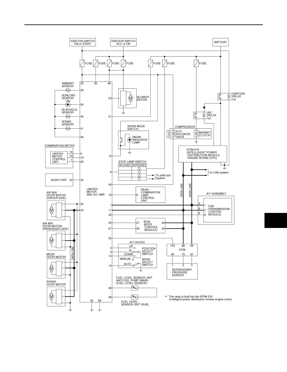
UNIFIED METER AND A/C AMP
DI-27
< SERVICE INFORMATION >
C
D
E
F
G
H
I
J
L
M
A
B
DI
N
O
P
Schematic
INFOID:0000000001328457
CONSULT-III Function (METER/M&A)
INFOID:0000000001328458
CONSULT-III can display each diagnostic item using the diagnostic test modes shown following.
TKWM4365E