Infiniti FX35 / FX45. Manual - part 274
CO-26
< SERVICE INFORMATION >
[VQ35DE]
WATER PUMP
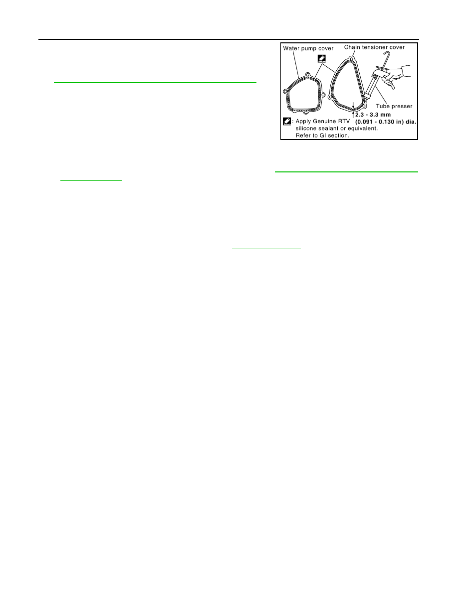
b.
Apply a continuous bead of liquid gasket with the tube presser
(commercial service tool) to mating surface of chain tensioner
cover and water pump cover.
Use Genuine RTV Silicone Sealant or equivalent. Refer to
GI-44, "Recommended Chemical Product and Sealant"
CAUTION:
Attaching should be done within 5 minutes after coating.
c.
Tighten mounting bolts.
5.
Install water drain plug (front) on water pump side of cylinder block.
• Apply liquid gasket to the thread of water drain plug (front).
Use Genuine RTV Silicone Sealant or equivalent. Refer to
GI-44, "Recommended Chemical Prod-
.
6.
Install in the reverse order of removal for remaining parts.
• After starting engine, let idle for three minutes, then rev engine up to 3,000 rpm under no load to
purge air from the high-pressure chamber of chain tensioner. Engine may produce a rattling
noise. This indicates that air still remains in the chamber and is not a matter of concern.
INSPECTION AFTER INSTALLATION
• Check for leaks of engine coolant using the radiator cap tester adapter (commercial service tool) and the
radiator cap tester (commercial service tool). Refer to
.
• Start and warm up the engine. Visually make sure that there is no leaks of engine coolant.
PBIC2663E