Infiniti FX35 / FX45. Manual - part 271
CO-14
< SERVICE INFORMATION >
[VQ35DE]
RADIATOR
4.
Remove reservoir tank and reservoir tank bracket.
5.
Disconnect A/T fluid cooler hoses from radiator.
• Install blind plug to avoid leakage of A/T fluid.
6.
Removal radiator hoses (upper and lower) and reservoir tank hose.
CAUTION:
Be careful not to allow engine coolant to contact drive belts.
7.
Remove radiator cooling fan assembly. Refer to
.
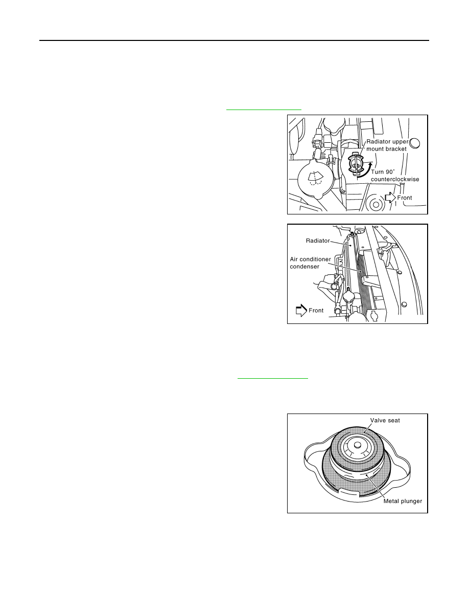
8.
Rotate two radiator upper mount brackets 90 degrees in the
direction shown in the figure, and remove them.
9.
Lift up and remove radiator.
CAUTION:
Do not damage or scratch A/C condenser and radiator core
when removing.
INSTALLATION
Installation is the reverse order of removal.
INSPECTION AFTER INSTALLATION
• Check for leaks of engine coolant using the radiator cap tester adapter (commercial service tool) and the
radiator cap tester (commercial service tool). Refer to
.
• Start and warm up the engine. Visually make sure that there is no leaks of engine coolant and A/T fluid.
Checking Radiator Cap
INFOID:0000000001325849
• Check valve seat of radiator cap.
- Check if valve seat is swollen to the extent that the edge of the
plunger cannot be seen when watching it vertically from the top.
- Check if valve seat has no soil and damage.
SBIA0447E
SBIA0448E
PBIC2816E