Index Infiniti Infiniti FX35 / FX45 (S50) - service repair manual 2008 year
Search
Content .. 257 258 259 260 ..
Infiniti FX35 / FX45. Manual - part 259
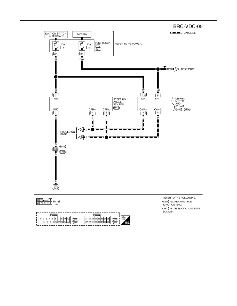
BRC-22
< SERVICE INFORMATION >
[VDC/TCS/ABS]
TROUBLE DIAGNOSIS
TFWM0234E