Infiniti FX35 / FX45. Manual - part 228
VEHICLE SECURITY (THEFT WARNING) SYSTEM
BL-179
< SERVICE INFORMATION >
C
D
E
F
G
H
J
K
L
M
A
B
BL
N
O
P
OK or NG
OK
>> Door switch circuit is OK, and go to “1 – 2 HOOD SWITCH CHECK”.
NG
>> GO TO 2.
2.
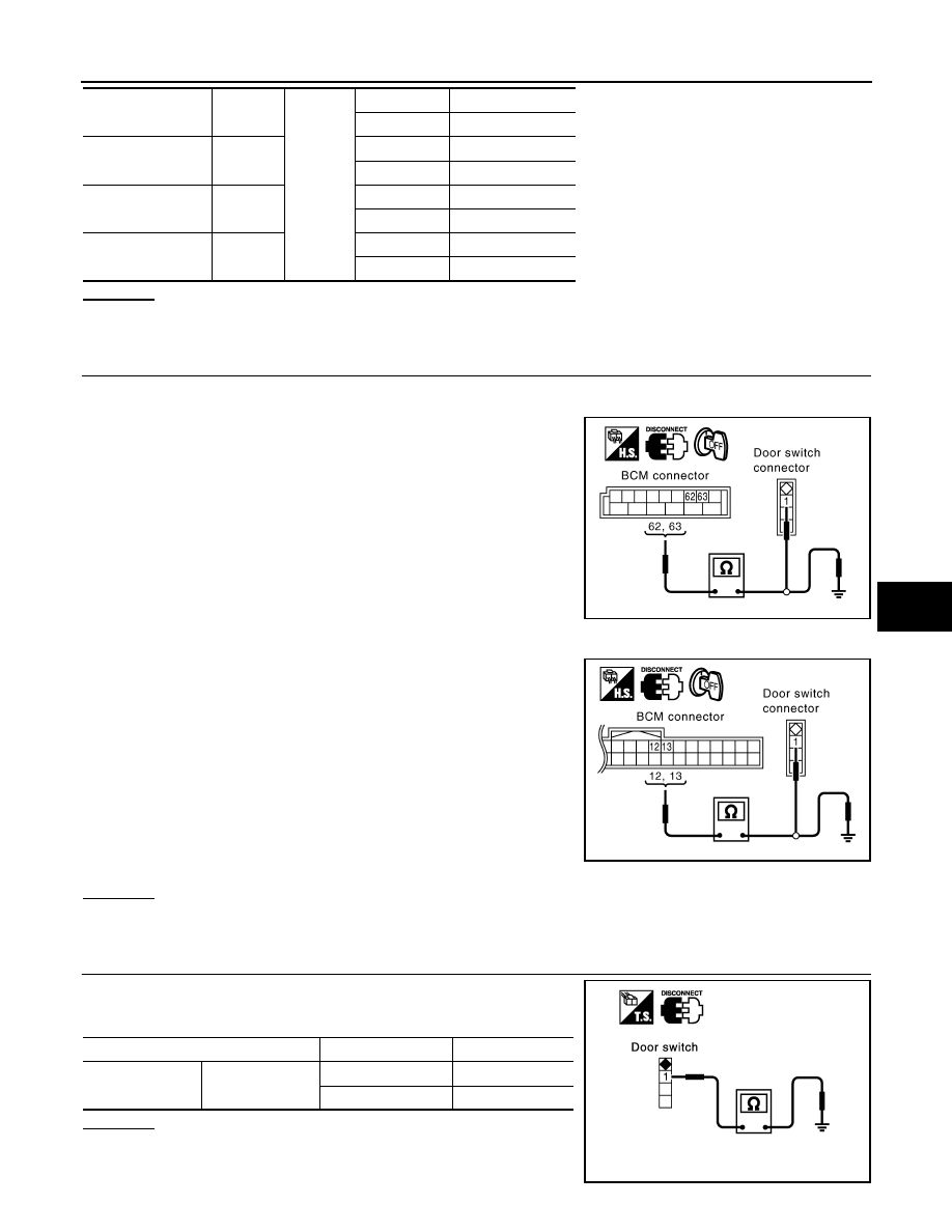
CHECK HARNESS CONTINUITY
1.
Turn ignition switch OFF.
2.
Disconnect BCM and door switches connector.
3.
Check continuity between BCM connector B14 terminals 62, 63
and door switch connector B26, B46 terminal 1, and ground.
4.
Check continuity between BCM connector M3 terminals 12, 13
and door switch connector B36, B206 terminal 1, and ground.
OK or NG
OK
>> GO TO 3.
NG
>> Repair or replace harness.
3.
CHECK DOOR SWITCH
Check continuity between each door switch terminal 1 and ground
part of door switch.
OK or NG
OK
>> GO TO 4.
NG
>> Replace malfunctioning door switch.
Front door switch
driver side
62 (W)
Ground
OPEN
0
CLOSE
Battery voltage
Front door switch
passenger side
12 (P/B)
OPEN
0
CLOSE
Battery voltage
Rear door switch
LH
63 (P)
OPEN
0
CLOSE
Battery voltage
Rear door switch
RH
13 (P/L)
OPEN
0
CLOSE
Battery voltage
BCM – Front door switch (driver side)
62 (W) – 1 (W)
: Continuity should exist.
BCM – Rear door switch LH
63 (P) – 1 (P)
: Continuity should exist.
BCM – Ground
62 (W) – Ground
: Continuity should not exist.
63 (P) – Ground
: Continuity should not exist.
PIIA6225E
BCM – Front door switch (passenger side)
12 (P/B) – 1 (SB)
: Continuity should exist.
BCM – Rear door switch RH
13 (P/L) – 1 (P)
: Continuity should exist.
BCM – Ground
12 (P/B) – Ground
: Continuity should not exist.
13 (P/L) – Ground
: Continuity should not exist.
PIIA6224E
Terminal
Condition
Continuity
1
Ground part of
door switch
Pushed
No
Released
Yes
PIIA3351E