Infiniti FX35 / FX45. Manual - part 172


  Index      Infiniti     Infiniti FX35 / FX45 (S50) - service repair manual 2008 year


Search            


Content   ..  170  171  172  173   ..


Infiniti FX35 / FX45. Manual - part 172


AV-142

< SERVICE INFORMATION >

NAVIGATION SYSTEM

Removal and Installation of GPS Antenna

INFOID:0000000001328772
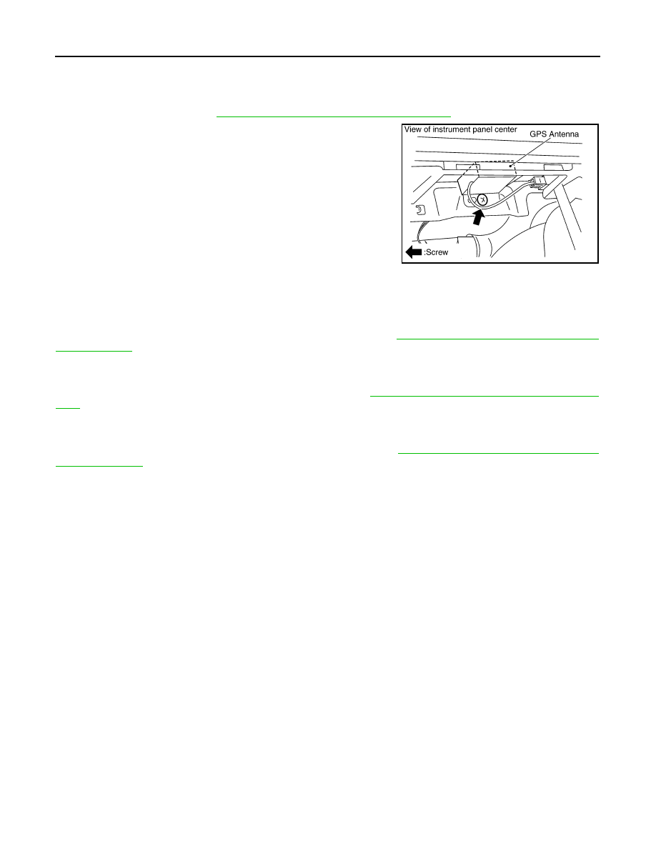
REMOVAL

1.

Remove audio unit. Refer to

AV-41, "Removal and Installation of Audio Unit"

.

2.

Remove screw (1) and remove GPS antenna.

INSTALLATION

Installation is the reverse order of removal.

Removal and Installation of A/C and AV Switch

INFOID:0000000001328773

For A/C and AV switch removal and installation procedures, refer to 

AV-42, "Removal and Installation for A/C

and AV Switch"

.

Removal and Installation of Display Unit

INFOID:0000000001328774

For display unit removal and installation procedures, refer to 

AV-42, "Disassembly and Assembly of Audio

Unit"

.

Removal and Installation of Display Control Unit

INFOID:0000000001328775

For display control unit removal and installation procedures, refer to 

AV-86, "Removal and Installation of Dis-

play Control Unit"

SKIA5824E

INFINITI MOBILE ENTERTAINMENT SYSTEM

AV-143

< SERVICE INFORMATION >

C

D

E

F

G

H

I

J

L

M

A

B

AV

N

O

P

INFINITI MOBILE ENTERTAINMENT SYSTEM

System Description

INFOID:0000000001328776

Refer to Owner's Manual for mobile entertainment system operating instructions.
Power is supplied at all times
• through 15A fuse (No. 32, located in the fuse and fusible link block)
• to DVD player terminal 16
• through DVD player terminals 31 and 32
• to DVD display terminals 15 and 16.
With the ignition switch in the ACC or ON position, power is supplied
• through 10A fuse [No. 6, located in the fuse block (J/B)]
• to DVD player terminal 15
• through DVD player terminal 21
• to DVD display terminal 5.
Ground is supplied
• to DVD player terminal 22
• through body ground B15 and B45
• to DVD player terminals 19, 27
• through DVD display terminals 6, 10 and 12.
When DVD player power switch is ON, power is supplied
• through DVD player terminal 9
• to audio unit terminal 38 and
• through audio unit terminal 40
• to DVD player terminal 11.
When DVD player power switch is ON, DVD sound signals are supplied
• through DVD player terminals 17, 18, and 20
• to DVD display terminals 1, 2 and 4.
DVD sound can be heard by the head phone.
When rear AV switch is ON, audio signals are supplied
• through DVD player terminals 1, 2, 3, and 4
• to audio unit terminals 37, 39, 43, and 42.
DVD sound can be heard from the speaker.
When DVD player power switch is ON, video signals are supplied
• through DVD player terminals 23 and 24
• to DVD display terminals 7 and 8.
When remote controller is operated, operation signals are supplied
• through DVD display terminal 14
• to DVD player terminal 30 and
• through DVD player terminal 29 
• to DVD display terminal 13.

Component Parts Location

INFOID:0000000001328777

SKIB8693E

AV-144

< SERVICE INFORMATION >

INFINITI MOBILE ENTERTAINMENT SYSTEM

Wiring Diagram - MES -

INFOID:0000000001328778

TKWM4430E

INFINITI MOBILE ENTERTAINMENT SYSTEM

AV-145

< SERVICE INFORMATION >

C

D

E

F

G

H

I

J

L

M

A

B

AV

N

O

P

TKWM4431E


Content   ..  170  171  172  173   ..