Infiniti FX35 / FX45. Manual - part 164
AV-110
< SERVICE INFORMATION >
NAVIGATION SYSTEM
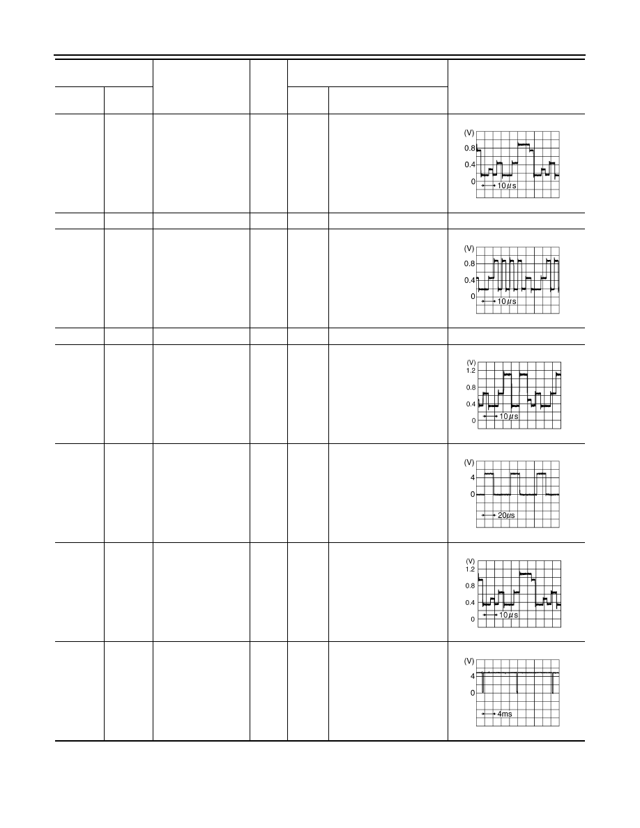
46 (R)
Ground
RGB signal (G: green)
Input
ON
Start Confirmation/Adjust-
ment (Navigation) mode,
and then display color bar by
selecting “Color Spectrum
bar” on Display Diagnosis
screen
47
—
Shield
—
—
—
—
48 (B)
Ground
RGB signal (B: blue)
Input
ON
Start Confirmation/Adjust-
ment (Navigation) mode,
and then display color bar by
selecting “Color Spectrum
bar” on Display Diagnosis
screen
49
—
Shield
—
—
—
—
50 (G)
Ground
RGB signal (R: red)
Output
ON
Start Confirmation/Adjust-
ment mode, and then dis-
play color bar by selecting
“Display Color Spectrum
Bar” on Display Diagnosis
screen
51 (B)
Ground
RGB area (YS) signal
Output
ON
Set the selector lever in R
position, and then display
the rear view image
52 (Y)
Ground
RGB signal (G: green)
Output
ON
Start Confirmation/Adjust-
ment mode, and then dis-
play color bar by selecting
“Display Color Spectrum
Bar” on Display Diagnosis
screen
53 (W)
Ground
Vertical
synchronizing (VP)
signal
Input
ON
—
Terminal
(Wire color)
Item
Signal
input/
output
Condition
Reference value
+
–
Ignition
switch
Operation
SKIB7361E
SKIB7362E
SKIB7769E
SKIB3599E
SKIB7770E
SKIB3598E