Infiniti FX35 / FX45. Manual - part 149
AV-50
< SERVICE INFORMATION >
ANTENNA
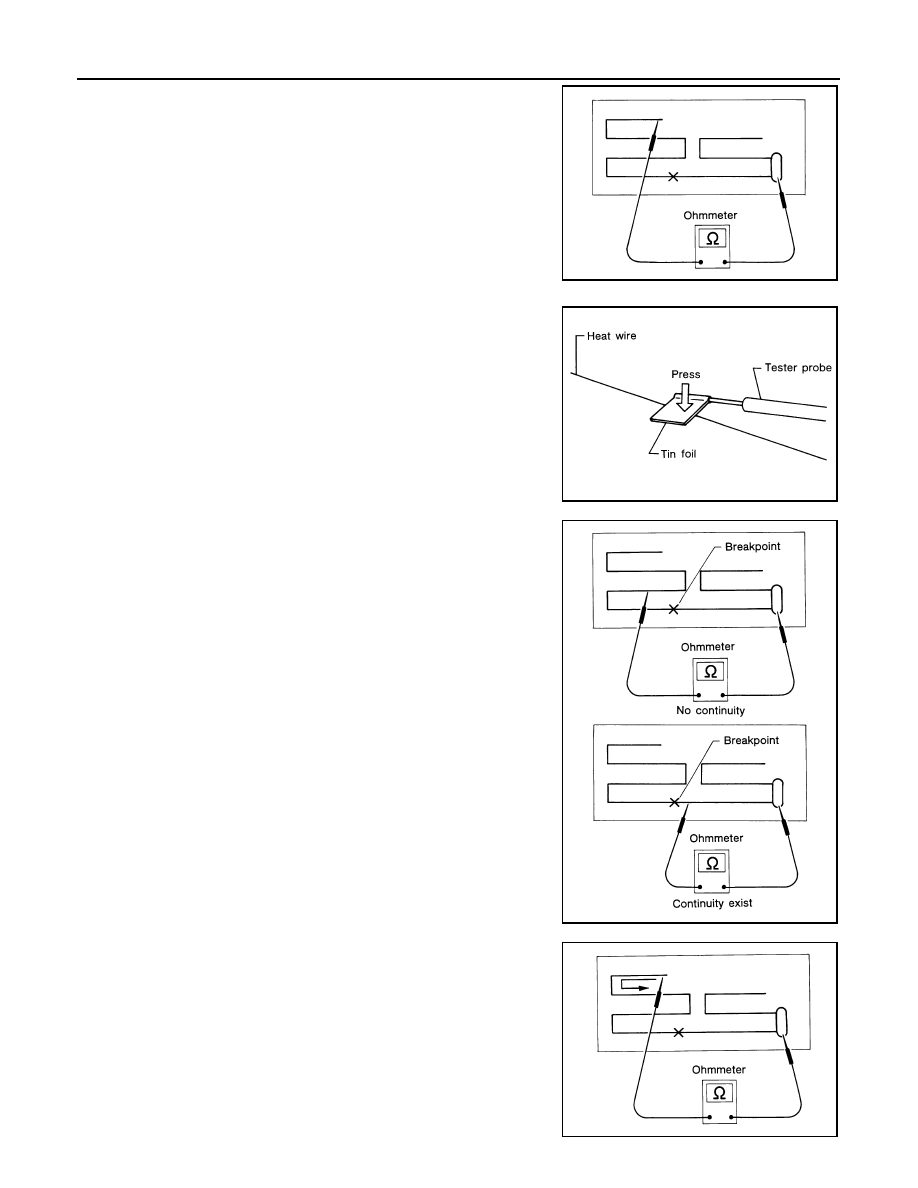
1.
Attach probe circuit tester (ohm setting) to antenna terminal on
each side.
• When measuring continuity, wrap tin foil around the top of
probe. Then, press the foil against the wire with your fin-
ger.
2.
If an element is broken, no continuity will exist.
3.
To locate a break, move probe along element. Tester needle will
swing abruptly when probe passes the broken point.
SEL250I
SEL122R
SEL252I
SEL253I