Infiniti FX35 / FX45. Manual - part 116
ATC-60
< SERVICE INFORMATION >
TROUBLE DIAGNOSIS
SYSTEM DESCRIPTION
Component Parts
Air mix door control system components are:
• Unified meter and A/C amp.
• Air mix door motor (LCU)
• A/C LAN system (PBR built-in mode door motor, air mix door motor and intake door motor)
• In-vehicle sensor
• Ambient sensor
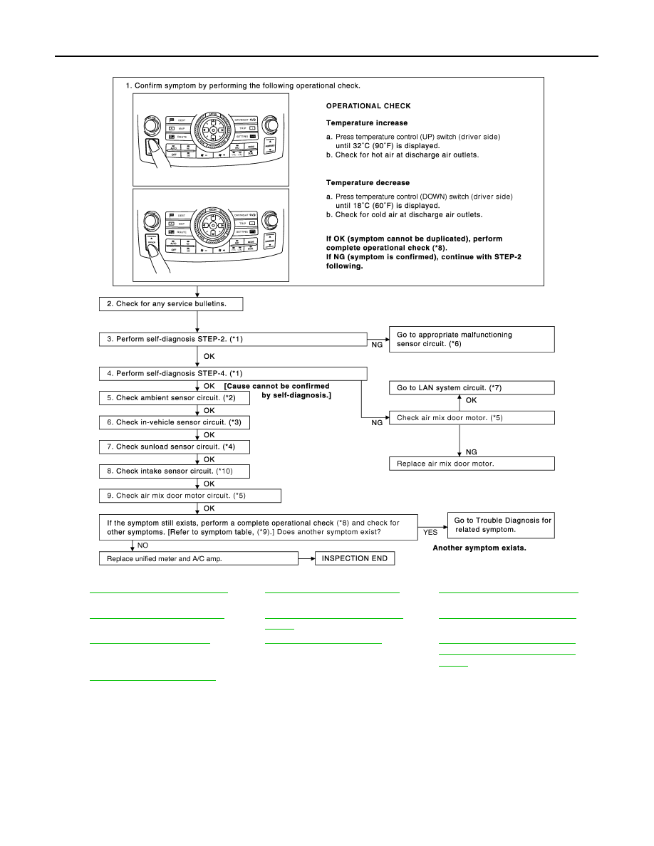
*1
ATC-43, "Self-Diagnosis Function"
see No. 4 to 6.
*2
ATC-86, "Ambient Sensor Circuit"
*3
ATC-88, "In-vehicle Sensor Circuit"
*4
ATC-91, "Sunload Sensor Circuit"
*5
ATC-62, "Air Mix Door Motor PBR
Circuit"
*6
ATC-43, "Self-Diagnosis Function"
see No. 13.
*7
.
*8
*9
ATC-32, "How to Perform Trouble
Diagnosis for Quick and Accurate
Repair"
*10
ATC-94, "Intake Sensor Circuit"
SJIA1586E